Headphone amplifier

a headphone amplifier and stereo technology, applied in the direction of amplifiers, transducer details, amplifier protection circuit arrangements, etc., can solve the problems of no effective separation between the circuitry and the battery source of power, large volume of the portable stereo headphone amplifier, etc., to improve convenience and use, improve the protection of the circuitry, and improve signal clarity

Active Publication Date: 2006-08-22
CHURCH OF SPIRITUAL TECH
View PDF8 Cites 3 Cited by
  • Summary
  • Abstract
  • Description
  • Claims
  • Application Information

AI Technical Summary

Benefits of technology

[0005]It is an object of the invention to provide a compact, external portable stereo headphone amplifier system having improved signal clarity.
[0006]It is a further object of the present invention to provide a compact, external portable stereo headphone amplifier having improved protection of its circuitry from damage caused by battery leakage.
[0007]It is a further object of the present invention to provide a compact, external portable stereo headphone amplifier having structural components arranged so as to provide for improved convenience and usefulness as a portable amplifier.
[0008]It is a further object of the present invention to provide a compact, external portable stereo headphone amplifier having improved separation between its battery source of power and its circuitry so as to minimize impact damage caused by momentum of the battery, and to maximize protection from damage caused by dirt particles or other debris from the battery compartment into the region of the housing which the circuitry is positioned.

Problems solved by technology

However, known portable stereo headphone amplifiers are relatively large, bulky, and have essentially all interior components mounted on a single side of a printed circuit board internal to a housing, extraneous controls and control circuitry and essentially no effective separation between the circuitry and a battery source of power.

Method used


Image

  • Headphone amplifier
  • Headphone amplifier
  • Headphone amplifier

Examples


Embodiment Construction

[0016]Preferred embodiments of the present invention will be described with reference to the accompanying drawings.

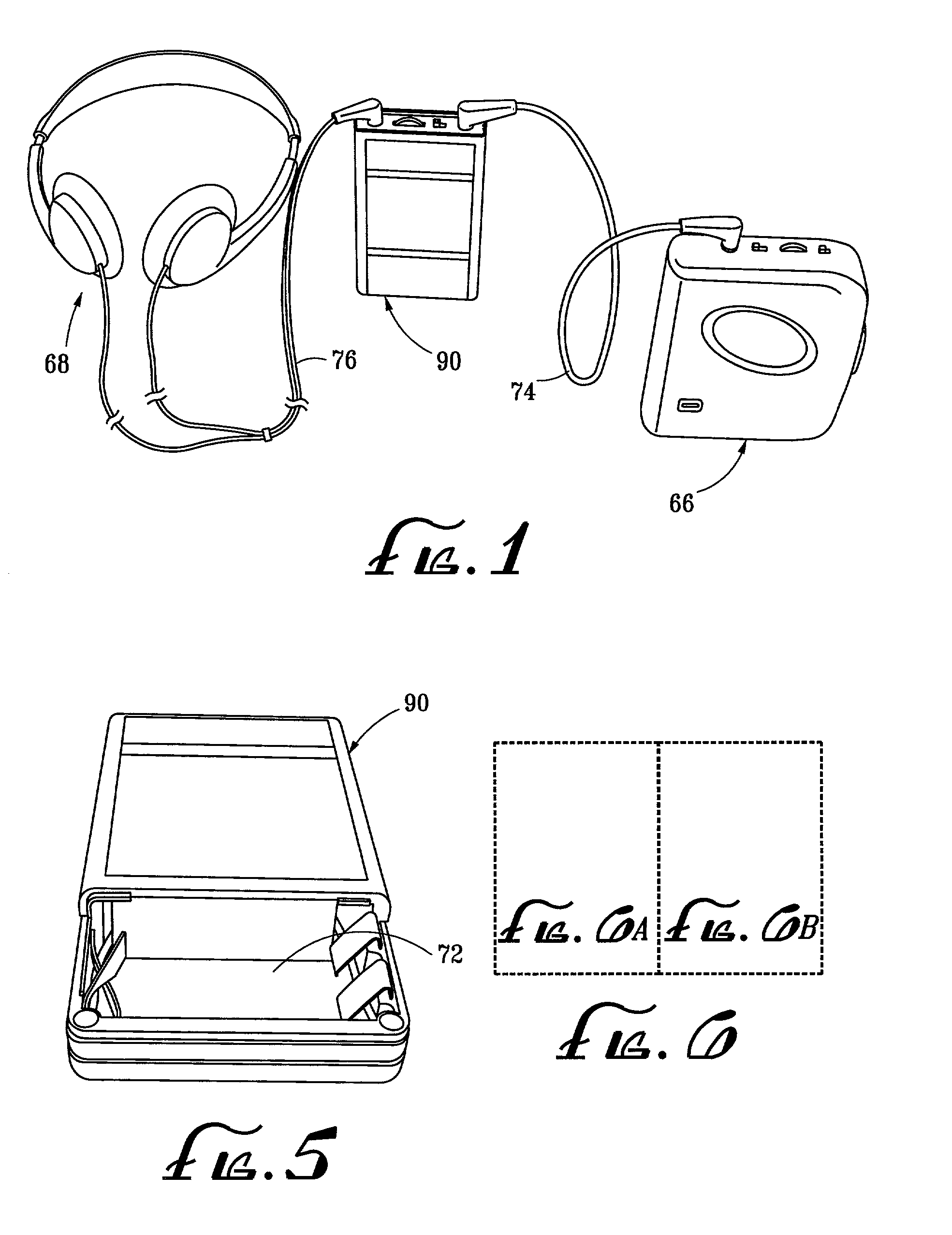
[0017]FIG. 1 illustrates the present stereo headphone amplifier system, including compact case or housing 90, the input of which amplifier is connected by conventional audio cable 74 to a stereo audio source 66 such as a conventional cassette tape or compact disc player. The output of the stereo amplifier is connected by conventional stereo headphone cable 76 to conventional headphones or earphones 68.

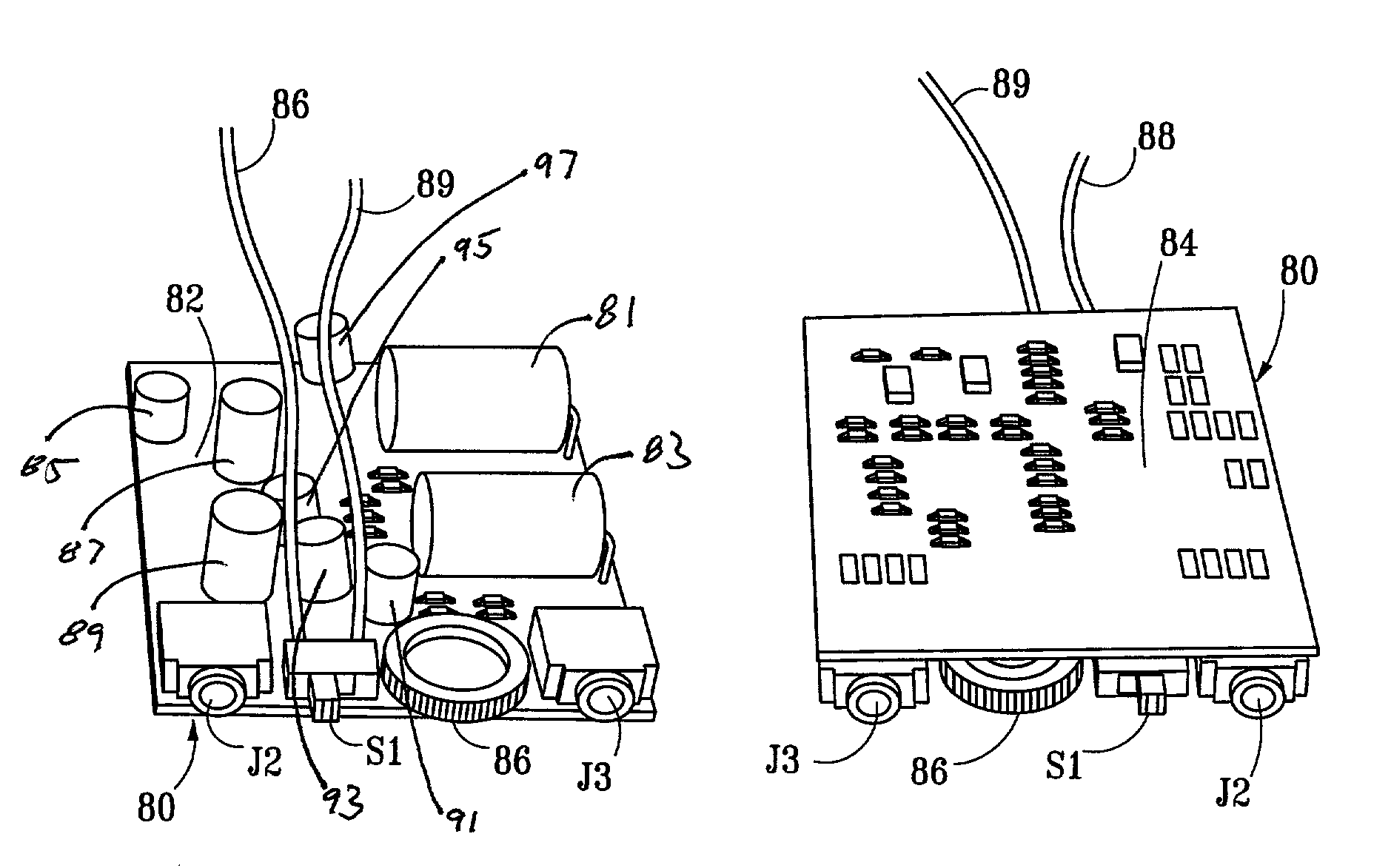
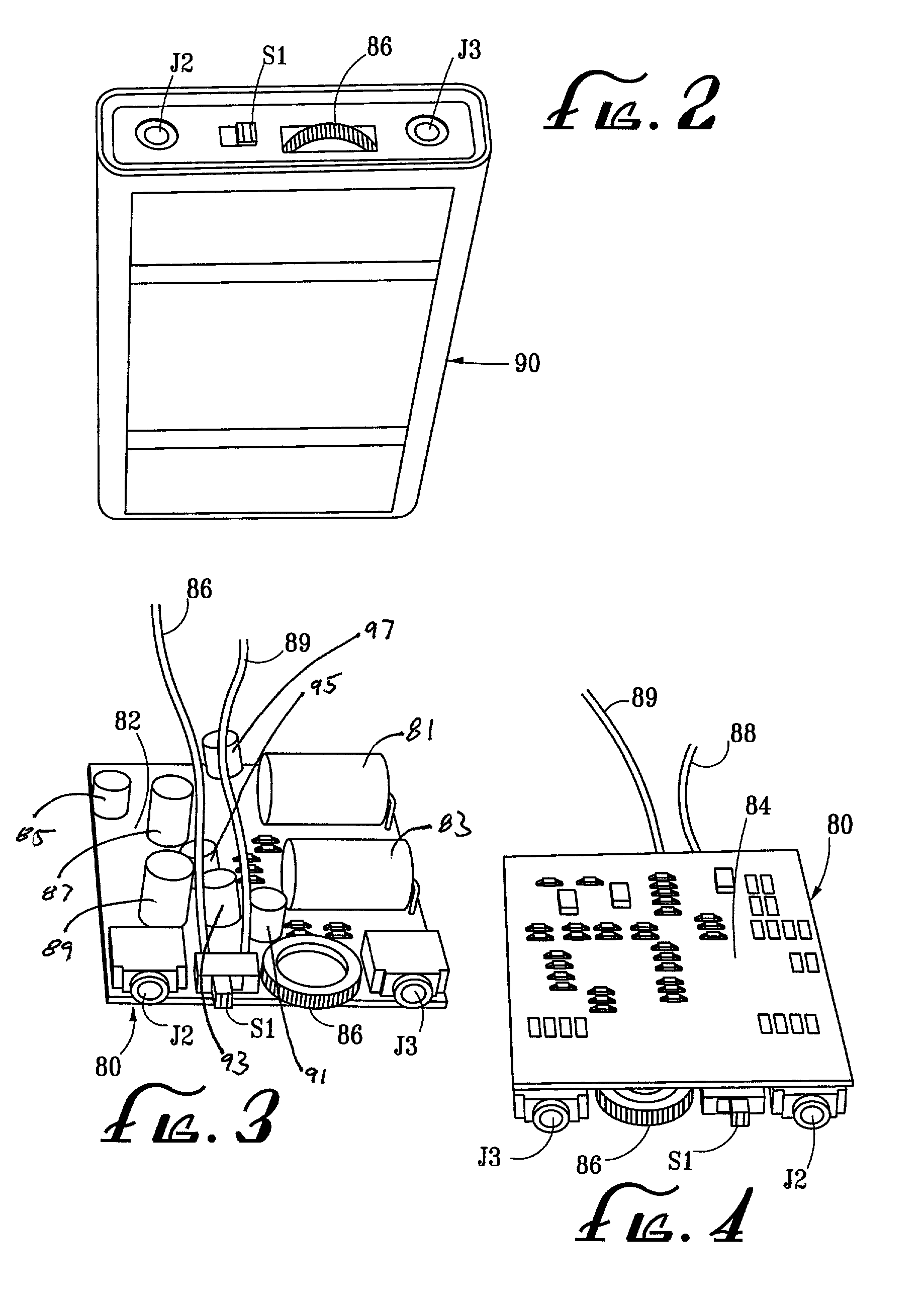
[0018]FIG. 2 is an external oblique view of the stereo amplifier case 90 showing its configuration and controls. In a preferred embodiment case 90 has overall external dimensions of approximately 2.4 inches by 4.2 inches by 0.9 inches. With respect to FIGS. 2 J2 and J3 show conventional 3 mm input and output audio jacks, respectively. Switch S1 is the power supply on / off switch. Volume control is provided by means of volume control wheel 86, which is rotatably connected to...


PUM


Abstract

A compact portable stereo headphone amplifier system for use with a conventional stereo audio source, such as a cassette or compact disc player, in which components are located on both sides of a circuit board and in which left channel components and right channel components are located on opposite sides of the circuit board thereby providing a compact unit.

Description

BACKGROUND OF THE INVENTION[0001]A. Field of the Invention[0002]The present invention relates to a portable stereo headphone system including headphones, stereo audio source and an amplifier external to the headphones and audio source.[0003]B. Description of the Prior Art[0004]External, portable stereo headphone amplifiers are known. However, known portable stereo headphone amplifiers are relatively large, bulky, and have essentially all interior components mounted on a single side of a printed circuit board internal to a housing, extraneous controls and control circuitry and essentially no effective separation between the circuitry and a battery source of power.OBJECTS AND SUMMARY OF THE INVENTION[0005]It is an object of the invention to provide a compact, external portable stereo headphone amplifier system having improved signal clarity.[0006]It is a further object of the present invention to provide a compact, external portable stereo headphone amplifier having improved protectio...

Claims


Application Information

Patent Timeline
Patent Type & Authority Patents(United States)
IPC IPC(8): H03F21/00H03F99/00H03F1/52H03F3/68
CPCH03F3/68H03F1/52
Inventor STINNETT, RICHARDTRUSSELL, ALBERT RAYBELLIN, RUSSELL D.
Owner CHURCH OF SPIRITUAL TECH
Why Eureka
Try Eureka