Beam forming method

a beamforming and beam technology, applied in the field of beamforming methods, can solve the problems of noise disturbance, short-term cancellation effect, signal transmission using electromagnetic waves, etc., and achieve the effect of reliably avoiding mutual cancellation

Inactive Publication Date: 2006-08-22
RPX CORP +1
View PDF16 Cites 18 Cited by
  • Summary
  • Abstract
  • Description
  • Claims
  • Application Information

AI Technical Summary

Benefits of technology

[0032]If the downlink signal delay is identical on two transmission paths, the subscriber station is unable directly to keep these two transmission paths for the signal received by it separate from one another. It is thus possible for these two components to be in antiphase at the subscriber station location, and hence to cancel one another out. Such mutual cancellation can be reliably avoided by producing a number of downlink signals at the base station from a user data sequence intended for that subscriber station, which downlink signals each have a different space time block coding, and each of these downlink signals is transmitted weighted with a different current weighting vector. In this way, each propagation path has a characteristic associated space time block coding, which makes it possible to distinguish between the components of the different transmission paths in all circumstances.

Problems solved by technology

Signals which are transmitted using electromagnetic waves are subject, inter alia, to disturbances due to interference during their propagation in a propagation medium.
Disturbances caused by noise may be caused, inter alia, by noise in the input state of the receiver.
Firstly, this means that a signal can arrive at the receiver more than once, in each case from different directions, with different delays, attenuations and phase angles, and, secondly, components of the received signal may be superimposed coherently with changing phase relationships in the receiver, leading to cancellation effects on a short-term timescale (fast fading) there.
Particular difficulties occur in the downlink direction, that is to say from the base station to the subscriber station, since the beamforming has to be carried out before the transmitted signals are influenced by the radio channel.
However, using this approach, it is impossible to prevent the possibility of interference on this transmission path leading to signal cancellation, and hence to interruptions in the transmission, in the short term.
One serious problem with this procedure is that the vector of the weighting factors which is estimated by the subscriber station must be transmitted to the base station and that, in accordance with the Recommendations from the 3GPP, only a narrow bandwidth of 1 bit per time slot (slot) is available for this purpose.
However, the known concepts reach their limits when the number of antenna elements at the base station is greater than 2, since the bandwidth which is required for transmission of the vector increases with its number of components, that is to say with the number of antenna elements.
This means that, although a large number of antenna elements would be desirable on the one hand in order to make it possible to align the transmission beam as accurately as possible, the limited available bandwidth on the other hand means that the weighting vector cannot be updated sufficiently often as would be necessary for matching to fast fading.

Method used


Image

  • Beam forming method
  • Beam forming method
  • Beam forming method

Examples


Embodiment Construction

[0040]Reference will now be made in detail to the preferred embodiments of the present invention, examples of which are illustrated in the accompanying drawings, wherein like reference numerals refer to like elements throughout.

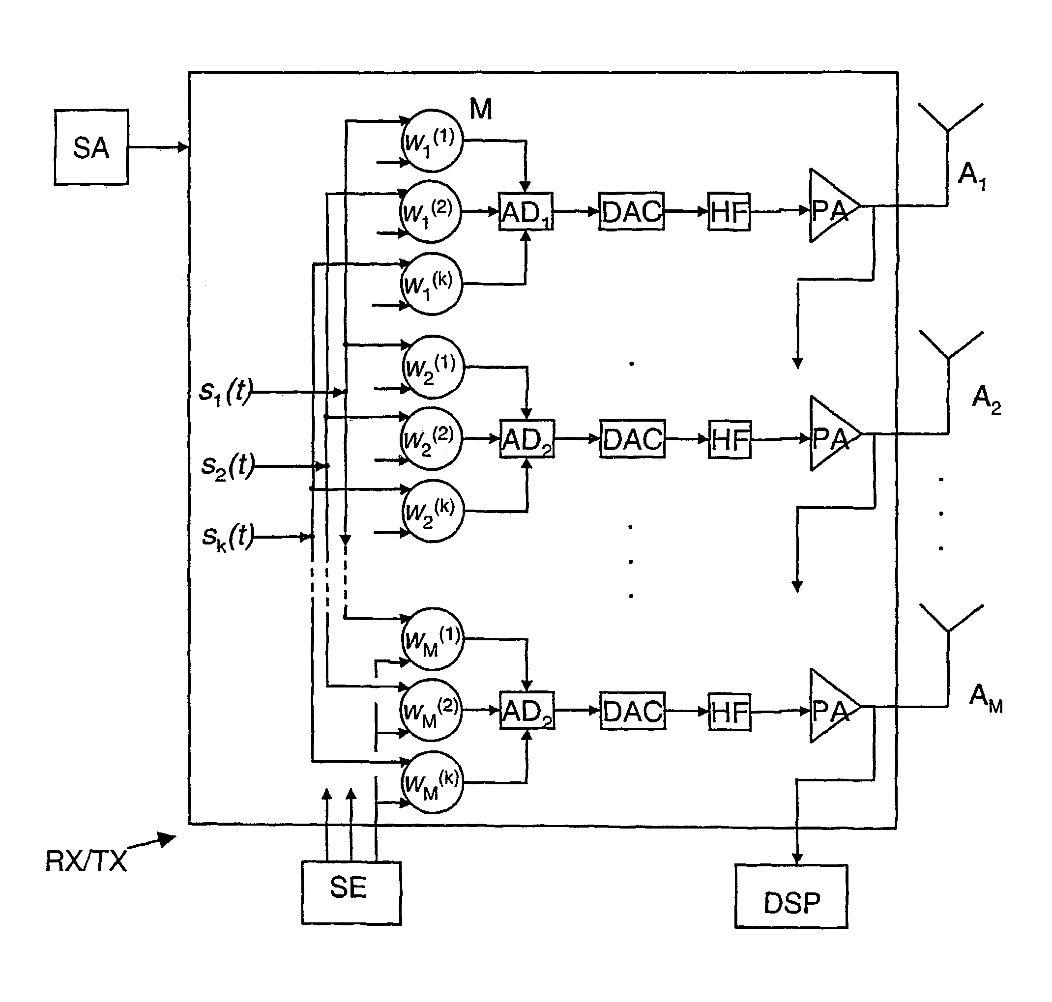
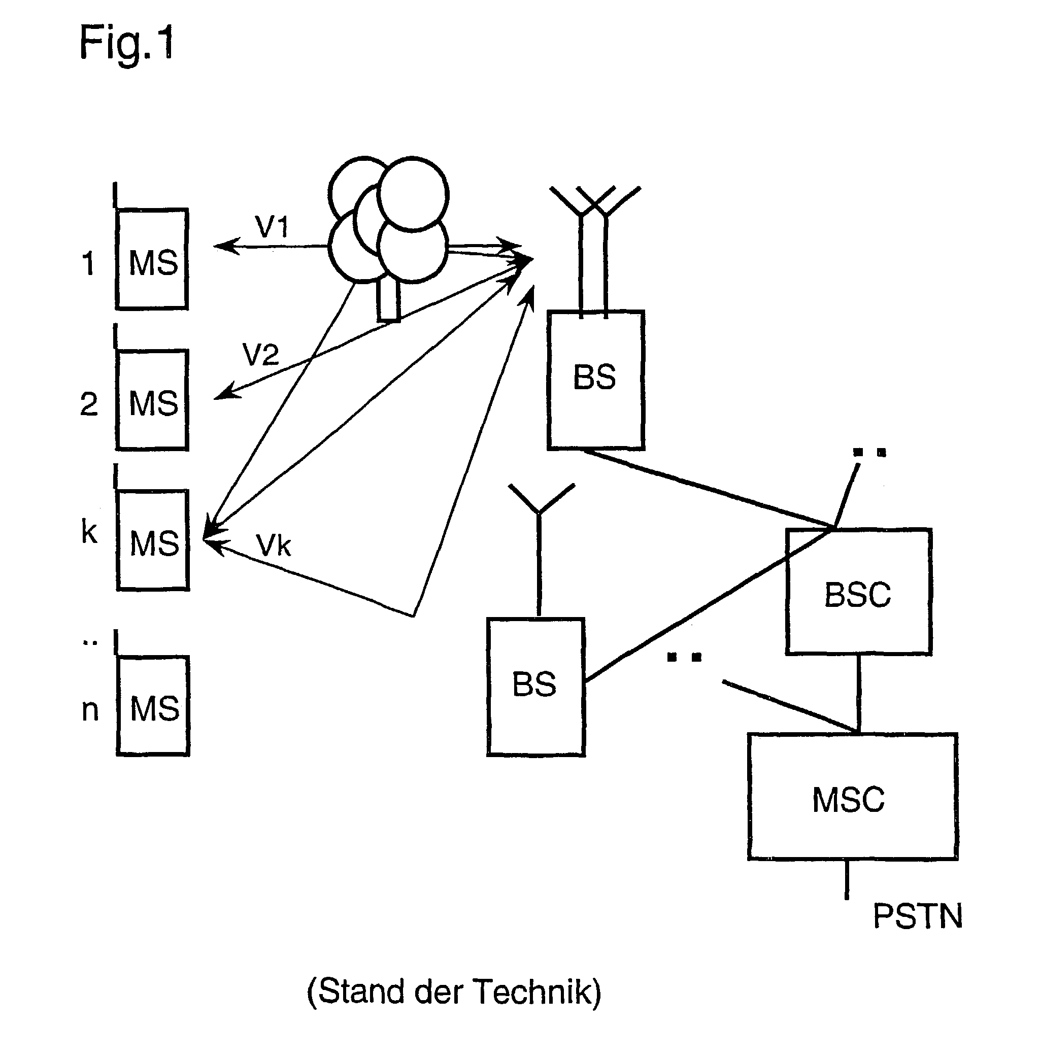
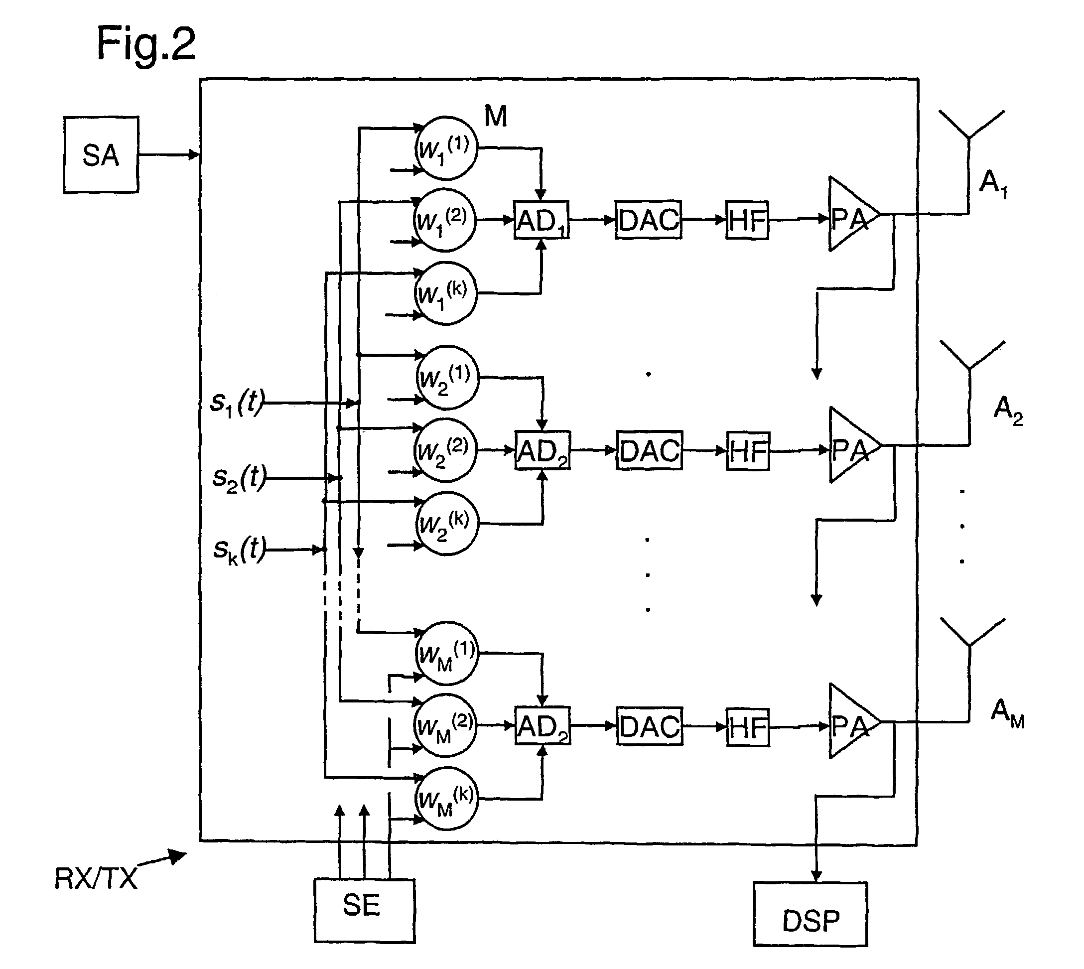
[0041]FIG. 1 shows the structure of a radio communications system in which the method according to the invention can be used. This system includes a large number of mobile switching centers MSC, which are networked with one another and provide the access to a landline network PSTN. Furthermore, these mobile switching centers MSC are connected to in each case at least one base station controller BSC. Each base station controller BSC in turn allows a connection for at least one base station BS. A base station BS such as this can set up a message link to subscriber stations MS via a radio interface. At least some of the base stations BS are for this purpose equipped with antenna devices AE which have a number of antenna elements (A1–AM).

[0042]FIG. 1 shows, by wa...


PUM


Abstract

In a radio communication system, a beam is formed between subscriber stations and a base station which has an antenna device with several antenna elements. The antenna elements emit a downlink signal based on respective weighing with coefficients of a weighting vector. A plurality of weighting vectors are determined at the subscriber station in an initialization phase and transmitted to the base station. In a subsequent working phase, the subscriber station selects a dominant weighting vector from the weighting vectors and transmits a designation of the selected weighting vector to the base station.

Description

CROSS REFERENCE TO RELATED APPLICATIONS[0001]This application is based on and hereby claims priority to German Application No. 100 26 077.2 filed on May 25, 2000, the contents of which are hereby incorporated by reference.BACKGROUND OF THE INVENTION[0002]The invention relates to a method for beamforming in a radio communications system having a base station whose associated antenna device has a number of antenna elements, so that spatial resolution is possible in the beamforming.[0003]In radio communications systems, messages (speech, picture information or other data) are transmitted via transmission channels by electromagnetic waves (radio interface). The transmission takes place both in the downlink direction from the base station to the subscriber station and in the uplink direction from the subscriber station to the base station.[0004]Signals which are transmitted using electromagnetic waves are subject, inter alia, to disturbances due to interference during their propagation i...

Claims


Application Information

Patent Timeline
Patent Type & Authority Patents(United States)
IPC IPC(8): H04B1/38H04M1/00H04B7/06H04B7/10H04B7/26H04J99/00
CPCH04B7/065H04B7/0634H04B7/0617
Inventor BRUNNER, CHRISTOPHERHAARDT, MARTINHAMMERSCHMIDT, JOACHIMSEEGER, ALEXANDER
Owner RPX CORP
Why Eureka
Try Eureka