Brake system with distributed electronic control units incorporating failsafe mode

a distributed electronic control and brake system technology, applied in the direction of braking components, computation using non-denominational number representation, process and machine control, etc., can solve the problems of essentially “, all three above-discussed prior art systems suffer from a number, and the functionality of this electronic control unit is limited, so as to respond to sensor input relatively quickly and free up resources

Inactive Publication Date: 2006-08-22
HALDEX BRAKE PROD AB
View PDF17 Cites 16 Cited by
  • Summary
  • Abstract
  • Description
  • Claims
  • Application Information

AI Technical Summary

Benefits of technology

[0017]Another object of the present invention is to provide an electrically controlled braking system having the above characteristics and which allows brake assemblies to respond to sensor input relatively quickly.
[0018]A further object of the present invention is to provide an electrically controlled braking system having the above characteristics and which does not require the central control unit to process all sensor inputs and to generate all control signals for all brake assemblies.
[0019]Still another object of the present invention is to provide an electrically controlled braking system having the above characteristics and which frees up the resources of the central control unit for the generation of control signals which affect many or all of the brake assemblies.

Problems solved by technology

However, all three of the above-discussed prior art systems suffer from a number of disadvantages.
One common disadvantage of all three systems is that the brake assemblies are essentially “dumb” in that no control signal generation is performed thereby.
While it is true that in the last of the above-described systems each of the brake assemblies may be provided with an electronic control unit, the functionality of this electronic control unit is limited, for example, to processing (e.g. translating) control signals received from the central control unit in order to cause the brake to actuate.
This is disadvantageous for several reasons.
As such, the time it takes for sensor signals to travel from the sensors to the central control unit, and then for the control signals, once generated, to travel from the central control unit to the brake assemblies may be relatively long, thereby causing the brake assemblies to respond to sensor input relatively slowly.
Another disadvantage of requiring the central control unit to process all sensor inputs and to generate all control signals for all brake assemblies is that the processing of a large number of sensor signals and the generation of a large number of control signals by a single processor may take a relatively long period of time.
This problem is exacerbated when the vehicle includes a large number of sensors and / or brake assemblies.
The disadvantage of all three of the above-described systems relating to the fact that the brake assemblies disclosed therein are essentially “dumb” (in that no control signal generation is performed thereby) may lead to additional problems as well.
In the near future, this approach to safety will reach its limit for two reasons: (1) The improved price / performance of the microelectronic components will make the implementation of fault-tolerant computer systems cheaper than the implementation of mixed (computer / mechanical) systems—as a consequence, there will be a cost pressure to eliminate the redundant mechanical system; and (2) As the performance of the computer controlled system is further improved, the fall-back to the inferior performance of the mechanical system increasingly constitutes a safety risk for the operator who is accustomed to the high performance of the computer controlled system.
If the vehicle condition no longer exists by the time the control signal which that condition prompted reaches the actuator, and the actuator acts upon that signal, the results may not only be unintended, but may actually be hazardous.
While this approach of ignoring untimely control signals may be more desirable than acting upon delayed signals, such an approach is still disadvantageous.
However, in known prior art systems having “dumb” system actuators, the actuators cannot make a determination of a proper action to be taken.

Method used


Image

  • Brake system with distributed electronic control units incorporating failsafe mode
  • Brake system with distributed electronic control units incorporating failsafe mode
  • Brake system with distributed electronic control units incorporating failsafe mode

Examples


Embodiment Construction

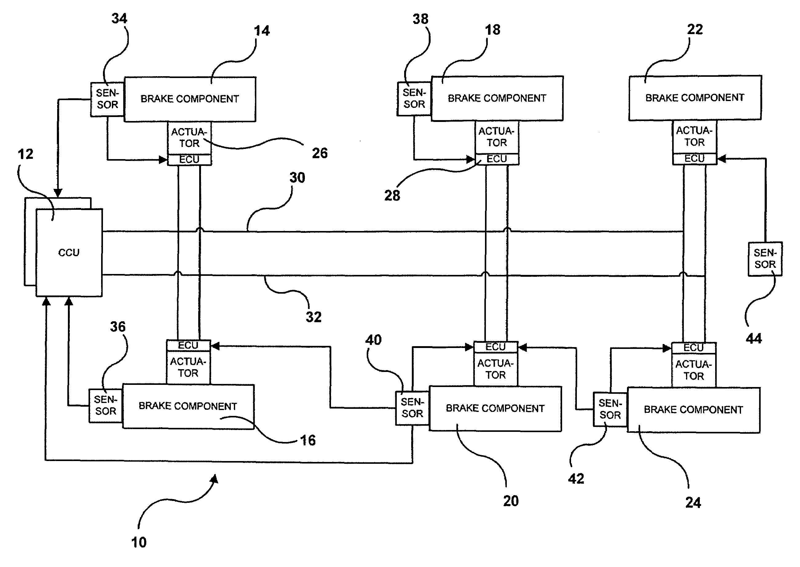
[0037]Referring first to FIG. 1, an electrically controlled braking system 10 in accordance with the present invention is shown. Braking system 10 includes at least one central control unit 12 which generates central control signals. Braking system 10 also includes a plurality of brake components 14, 16, 18, 20, 22, 24. While six brake components 14, 16, 18, 20, 22, 24 are shown in FIG. 1, it should be understood that braking system 10 may include a greater or lesser number of brake components.

[0038]Each of brake components 14, 16, 18, 20, 22, 24 is responsive to the central control signals generated by control unit(s) 12. More particularly, each of brake components 14, 16, 18, 20, 22, 24 includes a brake actuator 26 incorporating a distributed electronic control unit 28 which distributed electronic control unit 28 causes brake actuator 26 to operate in response to the central control signals generated by central control unit(s) 12. As this central control aspect of such electronica...


PUM


Abstract

A brake system for a heavy vehicle includes a control network, a brake component, a central control unit, and a distributed electronic control unit. The central control unit generates central control signals adapted to control the brake component, which control signals are transmitted to the brake component over the control network. The distributed electronic control unit receives the central control signals, controls the brake component in accordance with the central control signals if the central control signals are received during expected time periods, and controls the brake component in accordance with an alternative control scheme if the central control signals are not received during the expected time periods.

Description

CROSS-REFERENCE TO RELATED APPLICATIONS[0001]The present application is a continuation-in-part of currently pending U.S. patent application Ser. No. 10 / 672,807, filed Sep. 26, 2003.FIELD OF THE INVENTION[0002]The present invention relates generally to an electrically controlled braking system which is intended for use with wheeled vehicles, and more particularly to a control network for such a braking system which incorporates distributed electronic control units in addition to a central control unit.BACKGROUND OF THE INVENTION[0003]Traditional braking systems for motor vehicles include conventional hydraulic or pneumatic brakes associated with two or more wheels of the vehicle. Such conventional brakes are actuated by pressurized fluid or compressed air. When actuated, the brakes exert a force on a disk or drum which spins in conjunction with the wheel of the vehicle in order to create frictional forces which resist rotation of the wheel. Traditionally, control signals have been tr...

Claims


Application Information

Patent Timeline
Patent Type & Authority Patents(United States)
IPC IPC(8): B60T8/62B60T8/00B60T8/17B60T8/32B60T13/68B60T15/14B60T17/04B60W50/00
CPCB60T8/1708B60T8/321B60T8/885B60T13/683B60T13/686B60T15/14B60W2050/0004B60T2270/402B60T2270/404B60T2270/413B60T2270/82
Inventor NILSSON, PETERLINDQVIST, ANDERS
Owner HALDEX BRAKE PROD AB
Why Eureka
Try Eureka