Material testing system for turbines

a technology of material testing and turbines, which is applied in the direction of machines/engines, waterborne vessels, and using mechanical means, etc., can solve the problems of small quantities of abrasive materials in difficult and expensive and inability to completely remove small sand particles from the produced water stream

Inactive Publication Date: 2006-08-29
CONOCOPHILLIPS CO
View PDF42 Cites 4 Cited by
  • Summary
  • Abstract
  • Description
  • Claims
  • Application Information

AI Technical Summary

Benefits of technology

[0007]It is therefore an object of the present invention to provide an impeller testing method which allows for an accurate comparison of the wear resistance of various impeller materials and / or coatings so that an optimum material and / or coating can be determined. It should be understood that the above-listed object is only exemplary. Further, there is no requirement that this object be accomplished by the invention described and claimed herein.

Problems solved by technology

One common problem encountered when using a produced water stream for water flood operations is that the produced water stream can contain small quantities of abrasive materials.
Such small sand particles can be difficult and expensive to entirely remove from the produced water stream.
Thus, the produced water pumped to injection wells for water flooding operations inevitably contains at least a small amount of sand particles.
These sand particles can cause significant wear on the impellers of a multi-stage turbine pump used to pump the produced water to the injection well.
Although there has been much speculation as to which materials and / or coatings are best suited for constructing wear-resistant impellers, there has never been an adequate method for comparatively testing which materials or coatings work best in multi-stage turbine pumps used to pump produced water to injection wells.

Method used


Image

  • Material testing system for turbines
  • Material testing system for turbines
  • Material testing system for turbines

Examples


Embodiment Construction

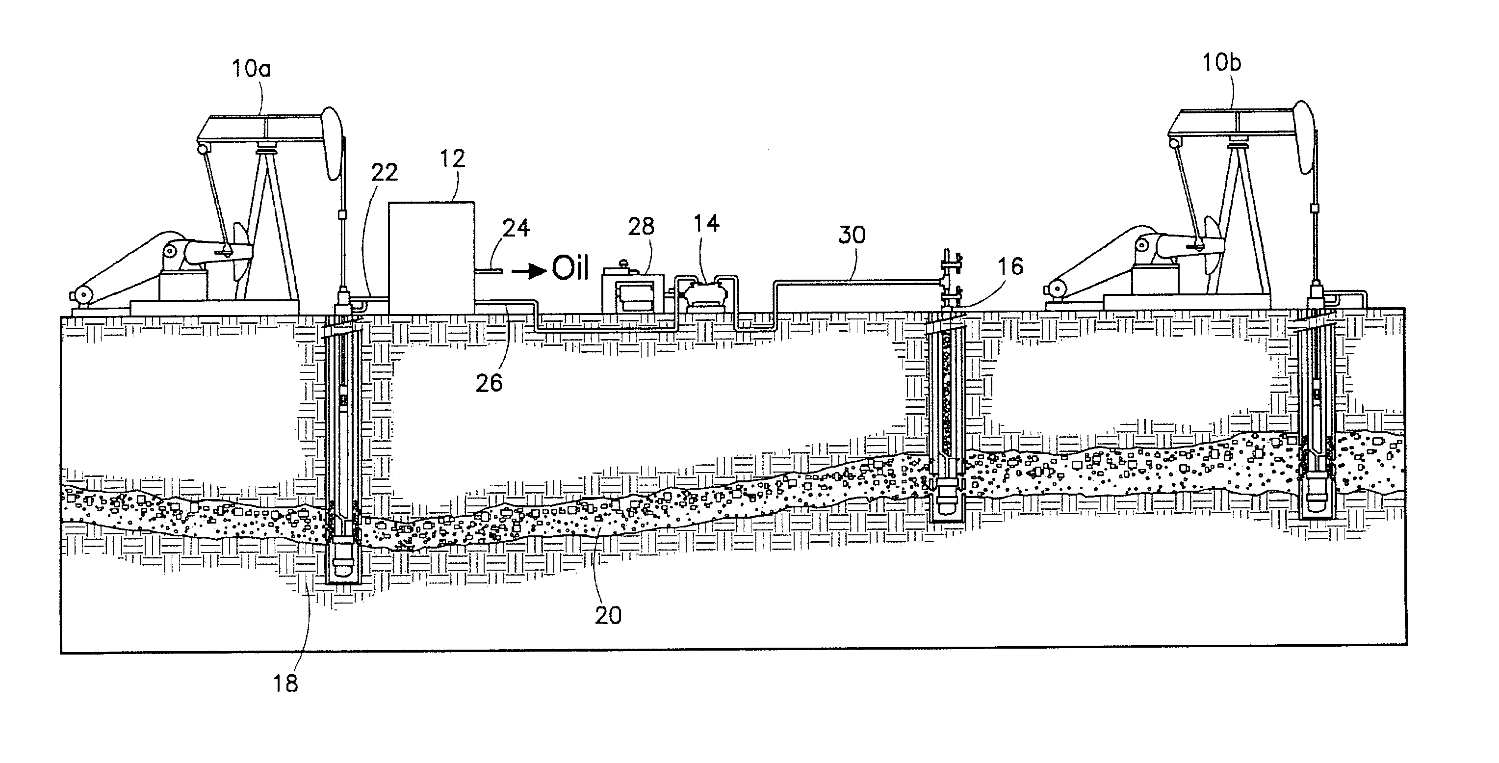
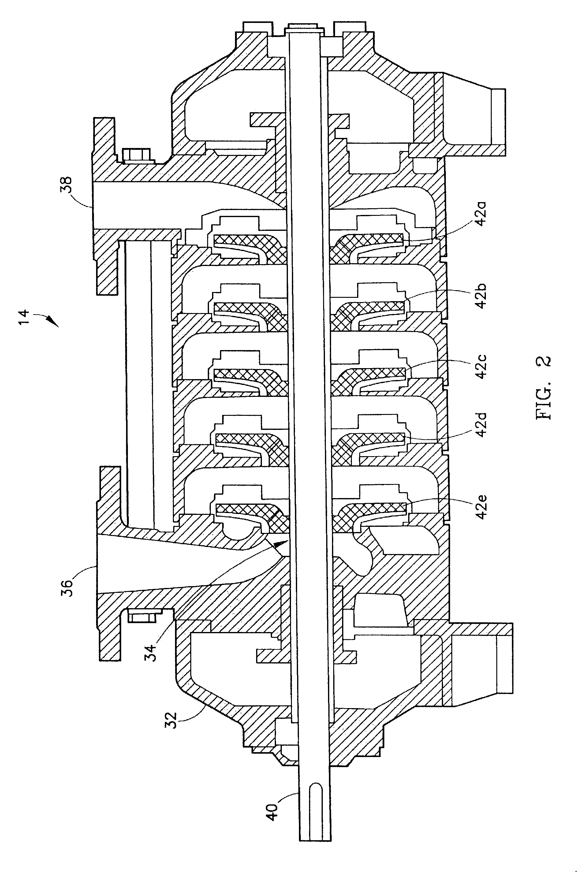
[0015]Referring initially to FIG. 1, a simplified petroleum production system is illustrated as including producing wells 10a,b an oilfield separation facility 12, an injection pump 14, and an injection well 16. Producing wells 10a,b extend into subterranean formation 18 and produce oil and water from a reservoir 20. The produced oil and water mixture is transported from first producing well 10a to separation facility 12 via conduit 22. In separation facility 12, the produced oil and water mixture is separated into an oil-rich stream which exits separation facility 12 via conduit 24 and a water-rich stream which exits separation facility 12 via conduit 26. Separation facility 12 can also be operable to separate a substantial portion of the sand particles present in the produced oil and water mixture entering separation facility 12 via conduit 22. Although separation facility 12 may remove a significant portion of the sand particles from the produced oil and water mixture, the water-...


PUM

PropertyMeasurementUnit
abrasiveaaaaaaaaaa
wear resistanceaaaaaaaaaa
physical propertiesaaaaaaaaaa

Abstract

The wear resistance of impellers used in multi-stage turbine pumps is tested by using a multi-stage turbine pump having impellers with different physical properties to pump a fluid containing small amounts of an abrasive material. After the fluid has been pumped for a time period sufficient to provide measurable wear to the impellers, the impellers are inspected to determine their relative resistance to wear.

Description

RELATED APPLICATIONS[0001]This application claims the priority benefit under 35 U.S.C. Section 119(e) of U.S. Provisional Patent Application Ser. No. 60 / 464,324, filed Apr. 21, 2003, the entire disclosure of which is incorporated herein by reference.BACKGROUND OF THE INVENTION[0002]1. Field of the Invention[0003]The present invention relates generally to multi-stage turbine pumps. In another aspect, the invention concerns a system for testing the wear resistance of impellers used in multi-stage turbine pumps.[0004]2. Description of the Prior Art[0005]Multi-stage turbine pumps are commonly employed in a variety of different applications. In one application, multi-stage turbine pumps are used as injection pumps for oilfield water flood operations. Frequently, the water pumped by the injection pump to the injection well is produced water that has previously been extracted from a subterranean formation along with oil, and subsequently separated from the oil.[0006]One common problem enco...

Claims


Application Information

Patent Timeline
Patent Type & Authority Patents(United States)
IPC IPC(8): G01N3/56F04D29/02G01N17/00G01M99/00G01N3/02
CPCG01N3/567G01N2203/0246
Inventor FEIERABEND, JERRY GLYNNBLUMER, DAVID J.AUSTIN, THOMASJOHNSON, SUNG-ISLOAN, RICHARD D.NEUGEBAUER, BRADLEY A.HEALD, RANDALL LEEJERLING, MARK F.BRADSHAW, PETER M.
Owner CONOCOPHILLIPS CO
Why Eureka
Try Eureka