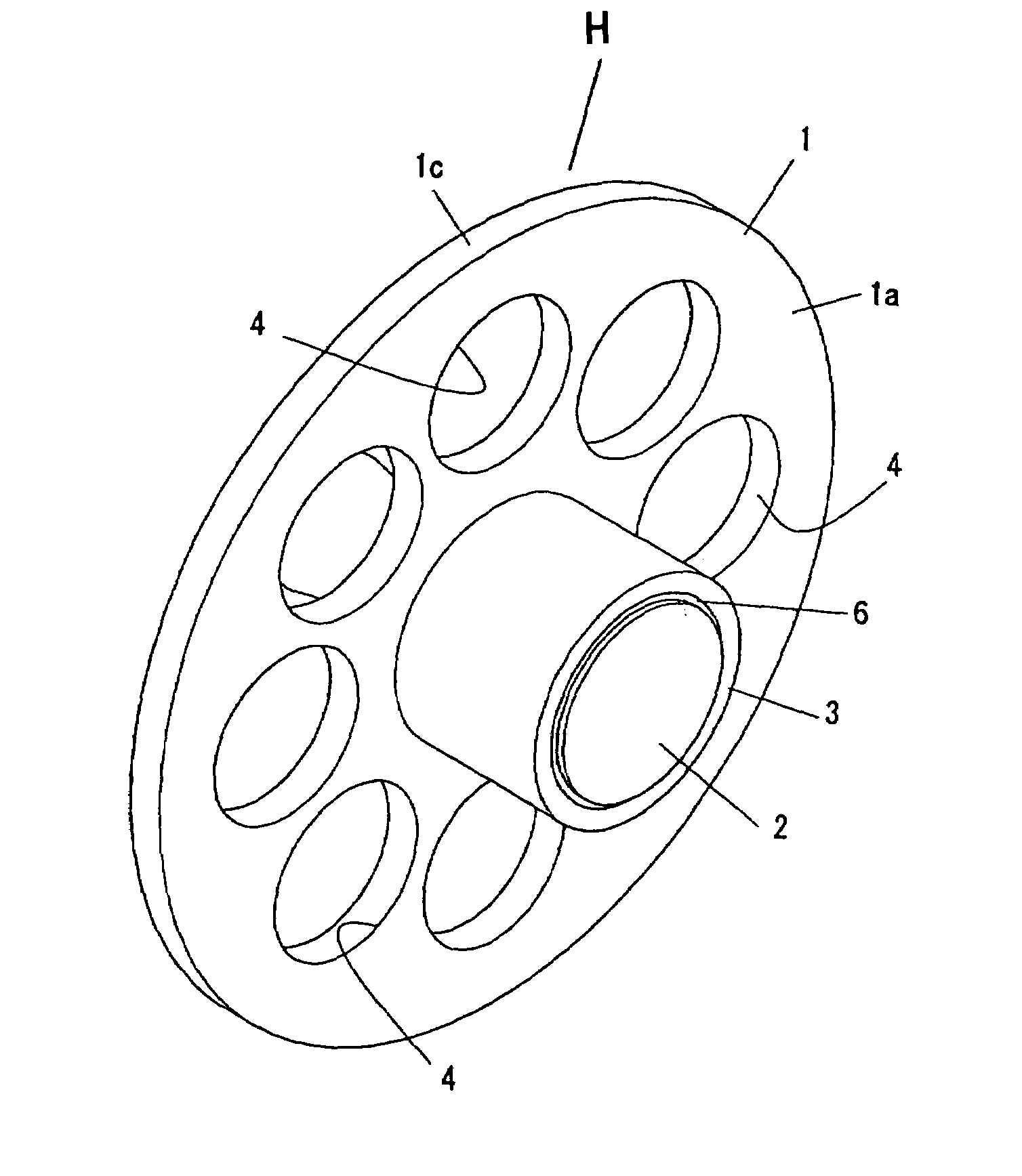
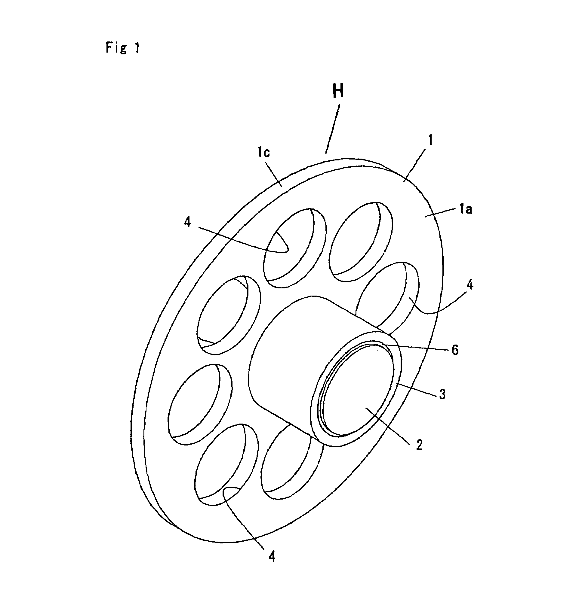
[0015]According to this hanger, since the hanger body has the substantially circular outer configuration, the inside of the collar of a shirt or of the
waist part of a skirt or trousers can be hung up over the hanger body in the circular shape even where the hanger is attached to the suspending place regardless of the direction. That is, the hanger body has no directionality due to the substantially circular outer configuration, resulting in enabling clothing to be hung up over the hanger body irrespective of the direction in which the hanger is suspended, thereby preventing the clothing from slipping or falling off due to an inclination of the hanger body or preventing a situation where the clothing cannot be hung up from occurring. Since it is unnecessary to confirm the vertical direction of the hanger and pay attention to the inclination of the hanger when suspending the hanger, cumbersomeness of suspension can be diminished. The substantially circular configuration includes a disk shape, a cylindrical shape, a polygonal shape having more corners to resemble a circle in appearance, and a polygonal shape with the corners rounded. In addition, since the first magnet is attached to one surface of the hanger body in a projecting manner, where the first magnet is arranged at a center or at a prescribed position of the hanger body, the hanger can be easily detached from the suspending place because the hanger body is inclined due to the principle of levers (i.e., leverage) with the first magnet as a fulcrum to separate part of the first magnet from the suspending place when pushing the circumference of the hanger body toward the suspending place
[0017]According to this hanger, since the first magnet is solely attached to the rear side of the hanger body at the substantially central position, pushing any position of the hanger body enables the hanger body to be inclined due to the principle of levers insofar as the position is away from the first magnet, thereby separating part of the first magnet from the suspending place, and thereby detaching the hanger from the suspending place easily. As the position at which the portion of the hanger body is pushed is farther from the first magnet, the hanger body can be inclined with a smaller force, and therefore, the position is desirably at the circumferential end of the hanger body.
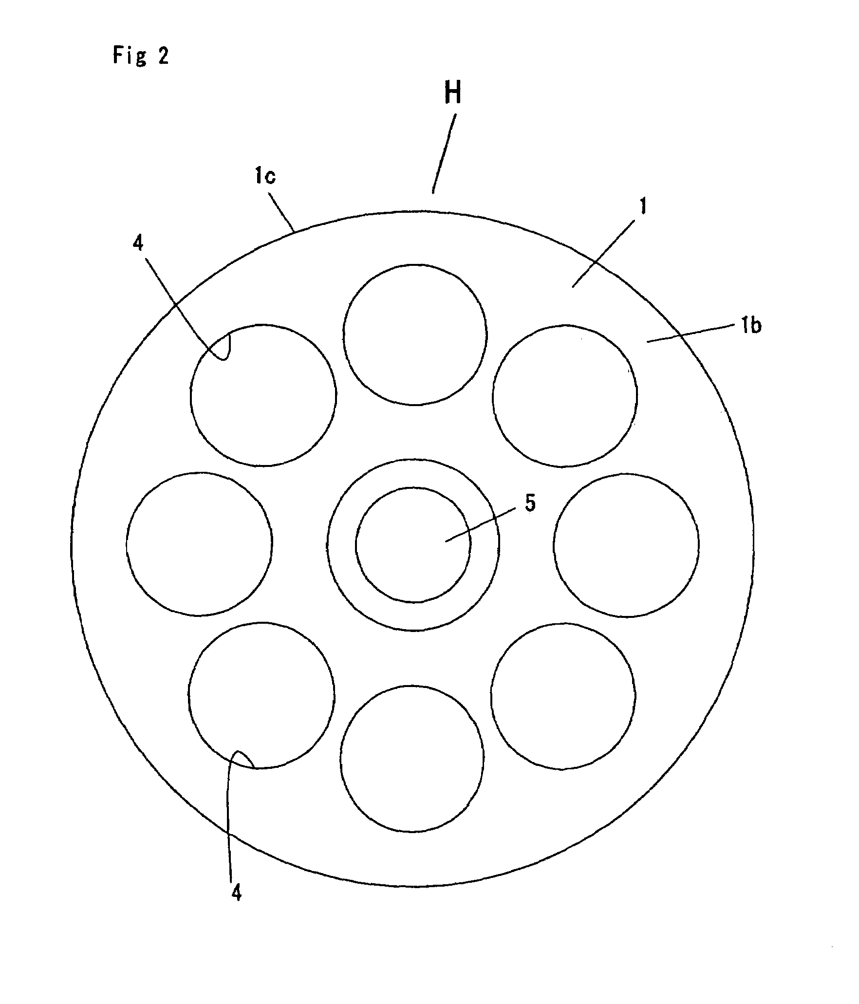
[0019]According to this hanger, since the hanger body is formed with a vent extending in the thickness direction of the hanger body, the air inside the clothing flows via the vent to ensure air ventilation to the clothing. Therefore, the clothing is amenable to
drying, and the inside of the clothing is prevented from being filled with
odor.
[0023]According to this hanger, where the attaching member is attached in advance to the suspending place via the attaching means, the first magnet of the hanger body is attracted to the second magnet of the attaching member. Where the attaching member is used, the hanger is attached with a stronger attraction force in comparison with where the attaching member is not used, because the hanger is attached to the suspending place as the first magnet of the hanger body and the second magnet of the attaching member are attracted to each other. That is, where the hanger is attached directly to the suspending place, the attraction force may not be enough because only the first magnet is attracted to the suspending place, so that the hanger may be detached from the suspending place or may slip off or fall off from the suspending place. To the contrary, with the hanger, since the magnets are attracted to each other, the hanger and the attaching member are firmly attached to each other, so that the hanger is hardly detached and hardly slips off or falls off. Moreover, a gap is formed by the thickness of the attaching member between the clothing and the suspending place, thereby improving air ventilation
[0025]Because the projection is formed as projecting toward a side of the hanger body at a position lower than the first magnet when the hanger is attached to the attaching member, the clothing is hooked up over the projection when the hanger on which the clothing is engaged is attached to the attaching member. Therefore, since the clothing is hung up not only over the hanger but also over the attaching member, the weight of the clothing is dispersed to the hanger as well as the attaching member, so that the hanger is hardly detached from, or slips and falls off from, the suspending place. In a case where a penlight or the like is inserted into a pocket of the clothing so as to make the clothing too heavy to keep the hanger at the surface of the attaching member, the projection can serve as a stopper to prevent the hanger from further slipping off the attaching member. The projection can be partly disposed at a position lower than the first magnet of the hanger body. If projections are disposed along the outer periphery of the attaching member so as to surround the first magnet of the hanger body, one of the protuberances is always disposed at a position lower than the first magnet even when the attaching member is attached to the suspending place in any direction. Therefore, this is desirable from the standpoint of convenience.
[0029]With this method, the attaching member is attached to the suspending place via the attaching means in advance, and the first magnet of the hanger is attracted to the second magnet. When this attaching member is used, the hanger can be attached to the suspending place with a stronger attraction force in comparison with a case where the hanger is attached to the suspending place without the use of the attaching member. That is, where the hanger is attached directly to the suspending place, attraction force may not be enough because only the first magnet is attracted to the suspending place, so that the hanger may be detached from the suspending place or may slip off or fall off from the suspending place. When the attaching member is used, however, since the magnets are attracted to each other, the hanger and the attaching member are firmly attached to each other, so that the hanger is hardly detached and hardly slips off or falls off. Moreover, a gap is formed by the thickness of the attaching member between the clothing and the suspending place, thereby improving air ventilation

