Electromechanical valve control actuator for internal combustion engines and internal combustion engine equipped with such an actuator

a technology of electric valve control and actuator, which is applied in the direction of non-mechanical valves, magnetic bodies, machines/engines, etc., can solve the problems of increasing the complexity and manufacturing costs of actuators, increasing the cost and complexity of actuator manufacture, and consuming considerable energy

Active Publication Date: 2006-08-29
PEZHO SITROEN AUTOMOBILS SA
View PDF25 Cites 10 Cited by
  • Summary
  • Abstract
  • Description
  • Claims
  • Application Information

AI Technical Summary

Benefits of technology

[0030]By fixing the magnet on the support of the electromagnet, the action of this magnet on the plate is also increased in relation to an analogous magnet incorporated in the body of the electromagnet, i.e., a magnet located at a greater distance from the plate.

Problems solved by technology

Due to the action of the magnet on the magnetic plate, such an electromagnet 106 or 108, called an electromagnet with magnet or polarized electromagnet, requires considerably less energy for controlling a valve, as the maintenance of a valve in a switched position represents a considerable energy consumption for the actuator.
Operations peculiar to the manufacture and the stocking of each of these subelements are therefore necessary, which increases the complexity and the manufacturing costs of the actuator.
Moreover, the operation required for assembling these subelements 106a and 106b with the magnet 116 increases the cost and the complexity of the manufacture of the actuator, and there is a risk during this assembly that the subelements 106a and 106b and / or the magnet 116 may be assembled incorrectly or that they will be damaged, which would reduce the performance of the electromagnet.
A new drawback is the difficulty of a possible replacement of a magnet 116 or 118.
Another drawback is the considerable size of the actuator 100, which is due especially to the fact that its height h is dictated by the cross section Sa of the magnets 116 and 118.
In addition, such an actuator has a considerable leakage due to the dispersion of the magnetic flux in the air gaps.
Second, the energy lost, e.g., in the form of the operating noise of the actuator due to the impact of the plate on the electromagnet is generally increased by an increase in the mass of the plate.
Such an increase in the energy loss causes a lower energy efficiency of the actuator.

Method used


Image

  • Electromechanical valve control actuator for internal combustion engines and internal combustion engine equipped with such an actuator
  • Electromechanical valve control actuator for internal combustion engines and internal combustion engine equipped with such an actuator
  • Electromechanical valve control actuator for internal combustion engines and internal combustion engine equipped with such an actuator

Examples


Embodiment Construction

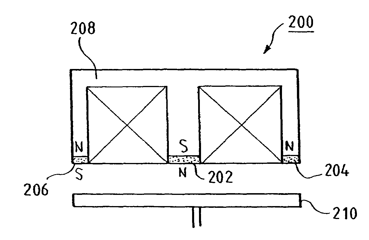
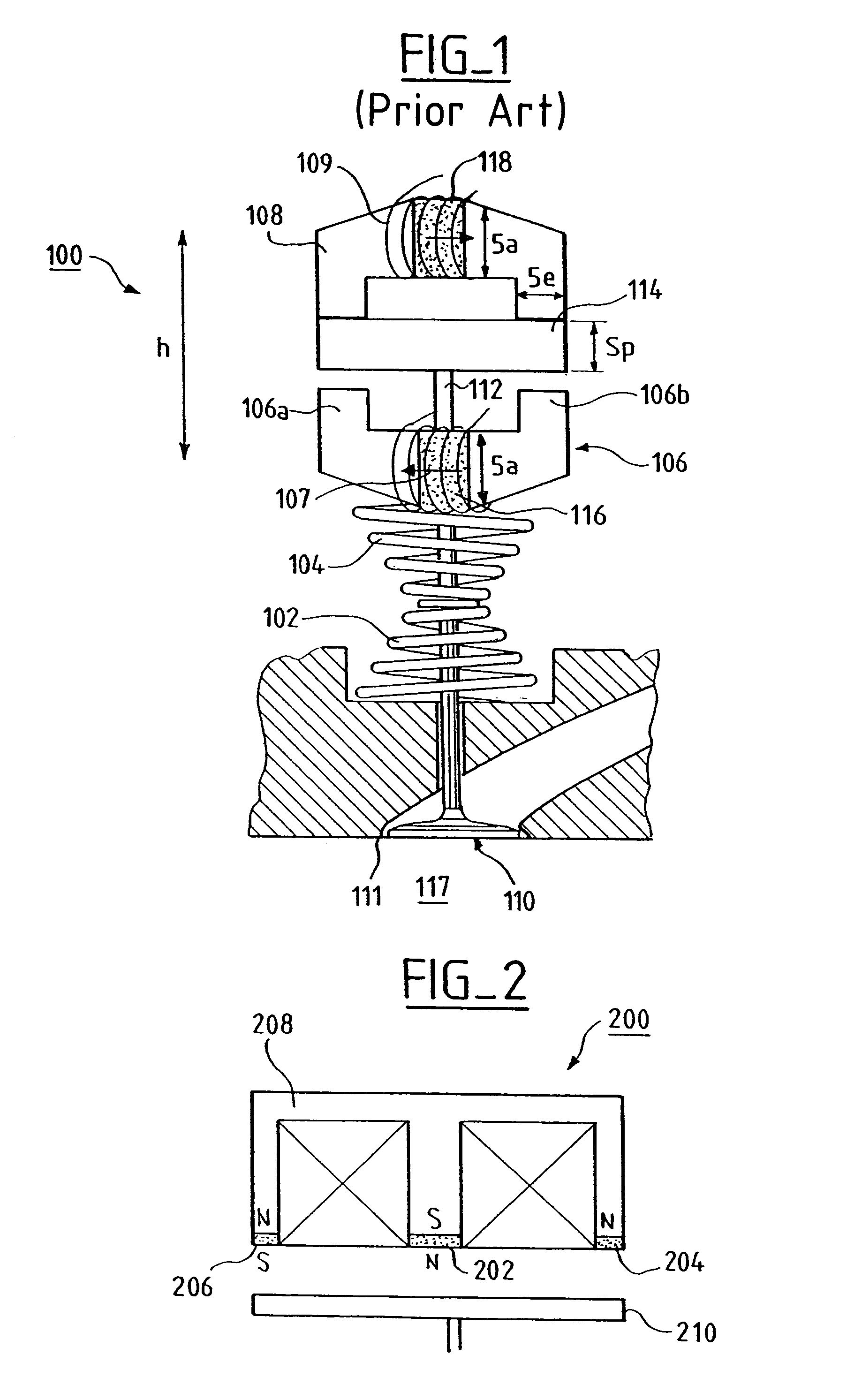
[0037]FIG. 2 shows an electromagnet 200 comprising three magnets 202, 204 and 206, which are located, according to the present invention, on the surface of the support 208 opposite the plate 210 of the actuator.

[0038]More precisely, the magnets 202, 204 and 206 are located, respectively, on the central branch and the end branches of the E-shaped support 208.

[0039]The magnets are arranged, as a function of their polarity, such that their magnetic fields support the magnetic field generated by the electromagnet 200 when the latter is active and attracts the plate 210.

[0040]In the example given, the north pole (N) of the magnet 202 and the south poles (S) of the magnets 204 and 206 point toward the plate 210.

[0041]Such an electromagnet 200 consequently requires an E-shaped support 208, as is used in the conventional manner for nonpolarized actuators.

[0042]In fact, the manufacture of such an E-shaped support is easy because it is formed by a single block. Moreover, the fixation on the s...


PUM

PropertyMeasurementUnit
magnetic fieldaaaaaaaaaa
displacementaaaaaaaaaa
energyaaaaaaaaaa

Abstract

An electromechanical valve control actuator for internal combustion engines, includes an electromagnet with a magnet and a mobile magnetic plate moving into the vicinity of the electromagnet. The magnet is located on a surface of the electromagnet opposite the plate. The actuator includes an E-shaped magnetic circuit, and the magnet is located at the end of a branch of this E-shaped circuit.

Description

FIELD OF THE INVENTION[0001]The present invention pertains to an electromechanical valve control actuator for internal combustion engines and to an internal combustion engine equipped with such an actuator.BACKGROUND[0002]An electromechanical actuator 100 (FIG. 1) for a valve 110 comprises mechanical means, such as springs 102 and 104, and electromagnetic means, such as electromagnets 106 and 108, for controlling the position of the valve 110 by means of electric signals.[0003]The rod of the valve 110 is applied for this purpose against the rod 112 of a magnetic plate 114 located between the two electromagnets 106 and 108.[0004]When current flows in the coil 109 of the electromagnet 108, the latter is activated and generates a magnetic field attracting the plate 114, which comes into contact with it.[0005]The simultaneous displacement of the rod 112 enables the spring 102 to bring the valve 110 into the closed position, the head of the valve 110 coming into contact with the seat 111...

Claims


Application Information

Patent Timeline
Patent Type & Authority Patents(United States)
IPC IPC(8): F16K31/02H01F7/00H01F7/08F01L9/20H01F7/06
CPCF01L9/04F01L2009/0451F01L2009/0448F01L2009/0436F01L2009/2151F01L2009/2148F01L2009/2136F01L9/20
Inventor SEDDA, EMMANUELFAGEON, CHRISTOPHEGUERIN, STEPHANEYONNET, JEAN-PAUL
Owner PEZHO SITROEN AUTOMOBILS SA
Why Eureka
Try Eureka