Sterile coupling

a technology of sterile coupling and coupling plate, which is applied in the field of sterile coupling plate, can solve the problem that the sterile filter is always a risk factor

Inactive Publication Date: 2006-08-29
CARIDIANBCT
View PDF22 Cites 58 Cited by
  • Summary
  • Abstract
  • Description
  • Claims
  • Application Information

AI Technical Summary

Benefits of technology

[0014]For avoiding entrapping air in the bonded area, one or both of the membrane devices may have grooves for letting out surplus air from the adhesive area before bonding.

Problems solved by technology

Such a sterile filter is always a risk factor.

Method used


Image

  • Sterile coupling
  • Sterile coupling
  • Sterile coupling

Examples


Embodiment Construction

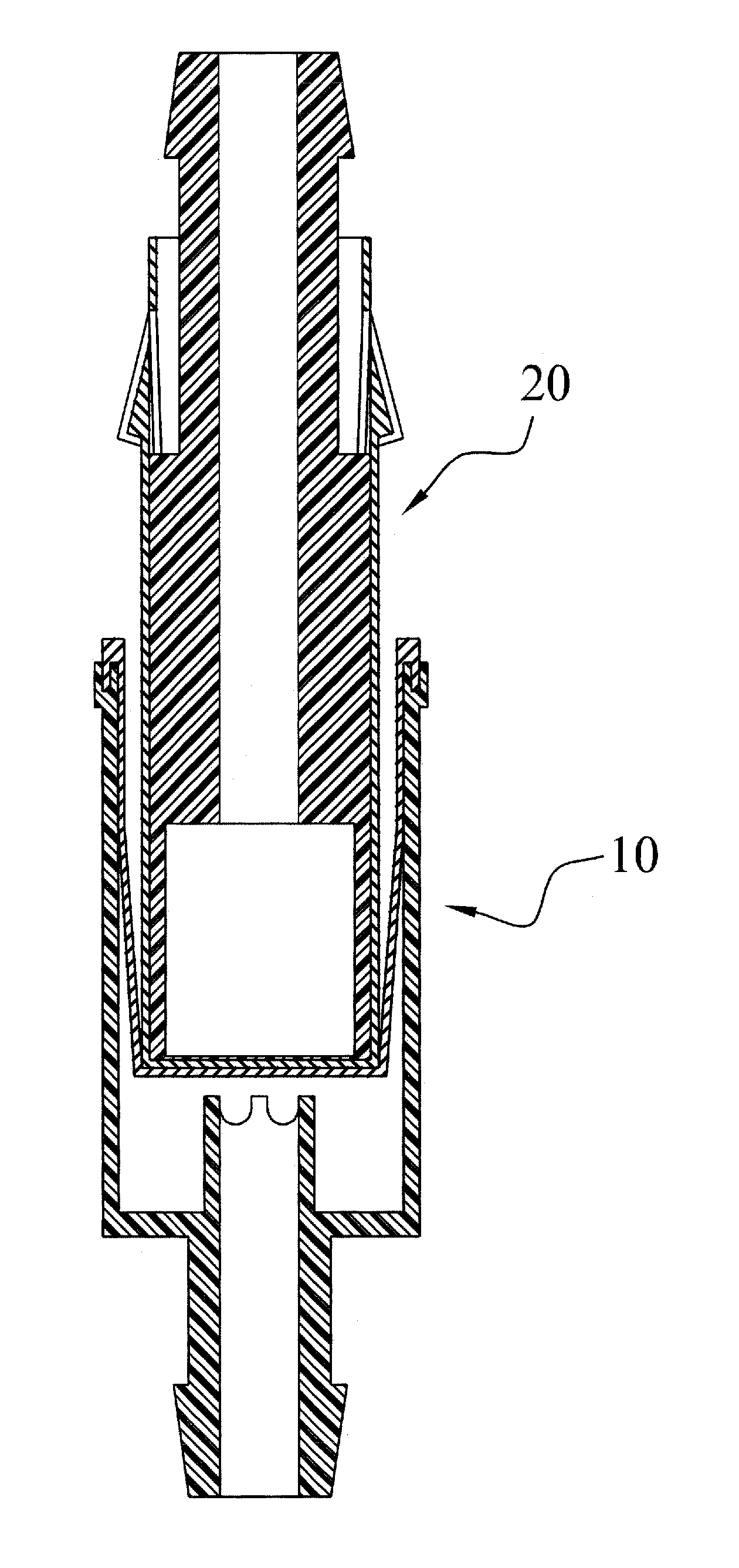
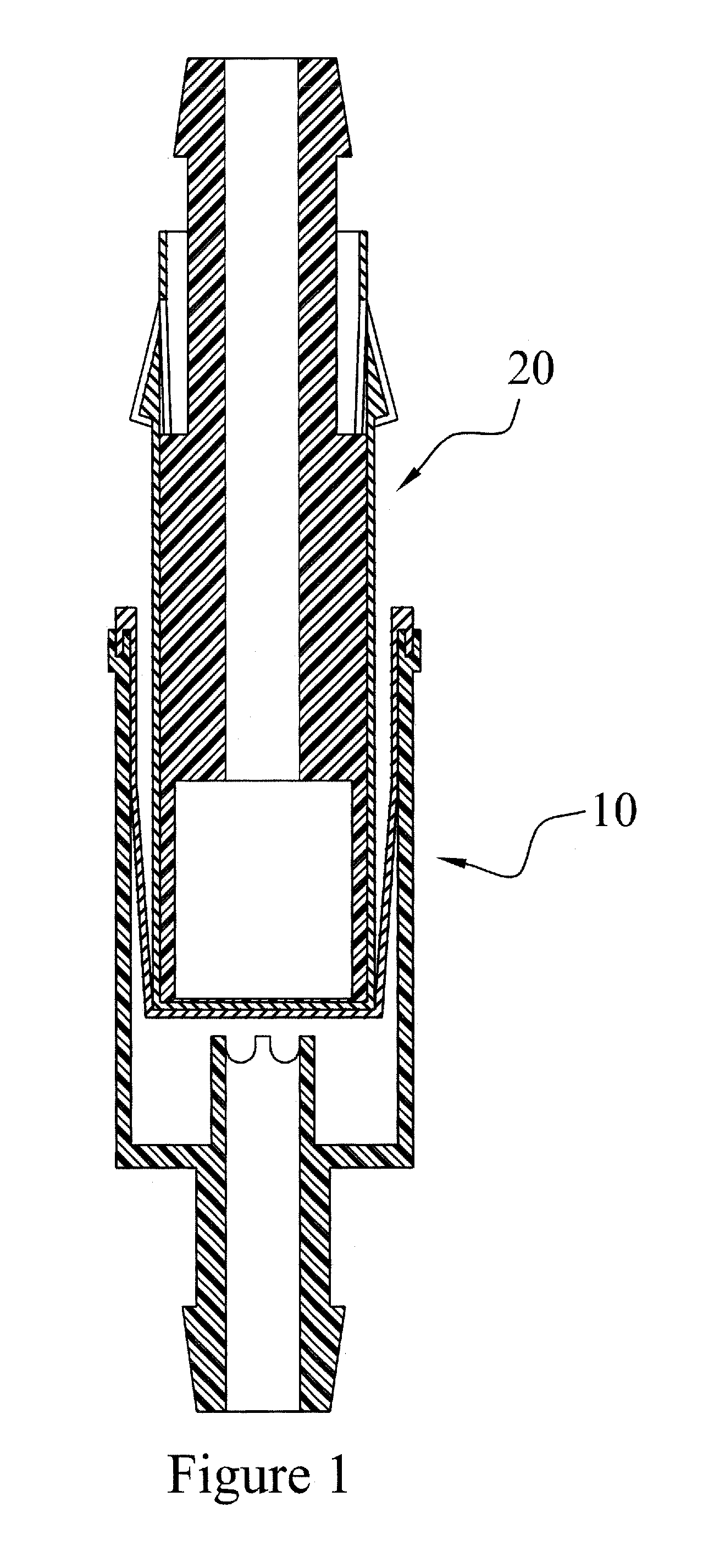
[0031]The major principle employed by the invention is that a sterile male connector is connected to a female connector in such a manner that no non-sterile areas can be reached by the gas or liquid that flows through the connected system, and no non-sterile air can come into contact with the gas or liquid being transferred.

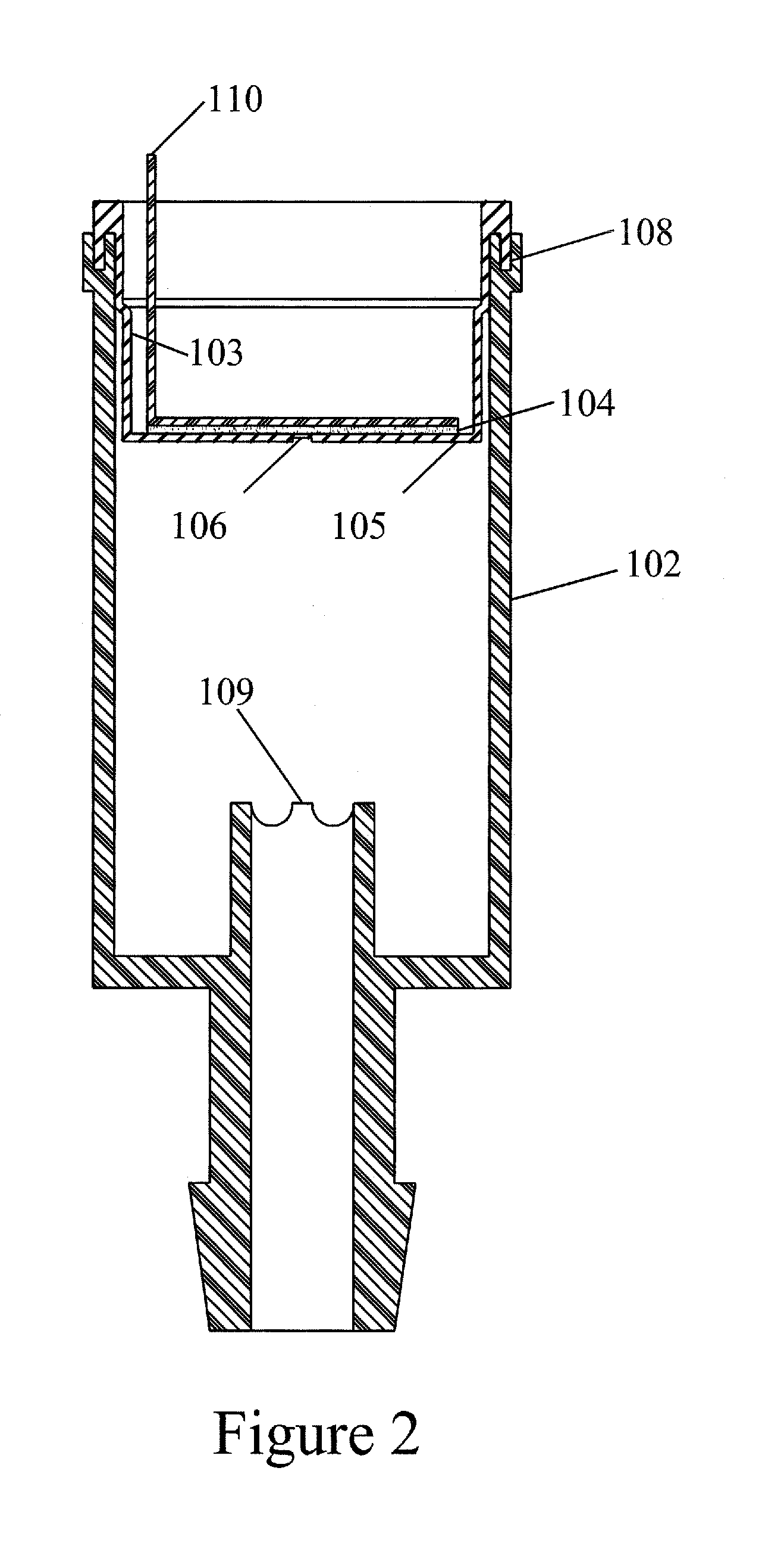
[0032]This principle is employed by a female and a male connector having a central (inner) zone that is the transfer channel and where each zone is protected by a rubber membrane and where the central part of these membranes are connected to each other as described more closely below.

[0033]Furthermore, one of the connectors incorporates a device for rupturing the membranes as they are arranged in the sterile zone. As the two couplings are pushed together, the membranes will touch it and then the rupturing device will cause them to rupture.

[0034]The construction is such that at the moment of rupture, the membranes are stretched and the membranes will retract to th...


PUM


Abstract

Sterile coupling comprising a male and a female connector, each provided with a membrane device comprising a membrane surface covered with an adhesive at the exterior surface. When the connectors are brought into operation, the adhesive surface are contacted to form a bonded surface. Then, a hole is generated through the bonded surface and the sterile portions of the devices are brought into cooperations. The hole is formed by a rupture member arranged in one of the connectors. After rupturing, the membrane devices retract to a space formed between the cylindrical bodies of the connectors.

Description

AREA OF INVENTION[0001]The present invention relates to a sterile coupling. The coupling is intended to be used in medical applications, such as at the interconnection and mixture of two initially sterile fluids, or sterile connection of bags or devices to catheters entered into the body of a mammal. One specific field of use is the interconnection of bags comprising blood components which are to be subject to treatment, such as rejuvenation of an erythrocyte cell suspension, or virus elimination of a blood component or whole blood.BACKGROUND ART[0002]Transferring sterile material, such as biological liquids (blood, blood products, sterile liquids to be infused, medicines etc) between different containers, is subject to the categorical requirement that sterility has to be maintained during the whole transfer process.[0003]Government requirements with respect to sterility can be summarized as follows: The sterile process shall be functionally equivalent to a “closed system” even thou...

Claims


Application Information

Patent Timeline
Patent Type & Authority Patents(United States)
IPC IPC(8): F16L35/00A61B19/00A61M39/02A61J1/20A61M39/14
CPCA61M39/14A61M39/18Y10S604/905A61M2039/1027
Inventor SPARRMAN, LEGAL REPRESENTATIVE, BIRGITTA EKMANWESTBERG, ERICUNGER, DECEASED, PETER
Owner CARIDIANBCT
Why Eureka
Try Eureka