Light guide plate and surface light source

a technology of light guide plate and surface light source, which is applied in the direction of lighting and heating apparatus, instruments, mechanical equipment, etc., can solve the problems of increased surface light source cost, increased surface light source size, and non-uniform illumination provided through the light emitting surface (not shown). to achieve the effect of high-quality illumination

Inactive Publication Date: 2006-08-29
HON HAI PRECISION IND CO LTD
View PDF5 Cites 57 Cited by
  • Summary
  • Abstract
  • Description
  • Claims
  • Application Information

AI Technical Summary

Benefits of technology

[0010]An object of the present invention is to provide a light guide plat

Problems solved by technology

Thus, the illumination provided through the light emitting surface (not shown) is non-uniform and a high-quality display image cannot be obtained in a liquid crystal display usin

Method used


Image

  • Light guide plate and surface light source
  • Light guide plate and surface light source
  • Light guide plate and surface light source

Examples


Embodiment Construction

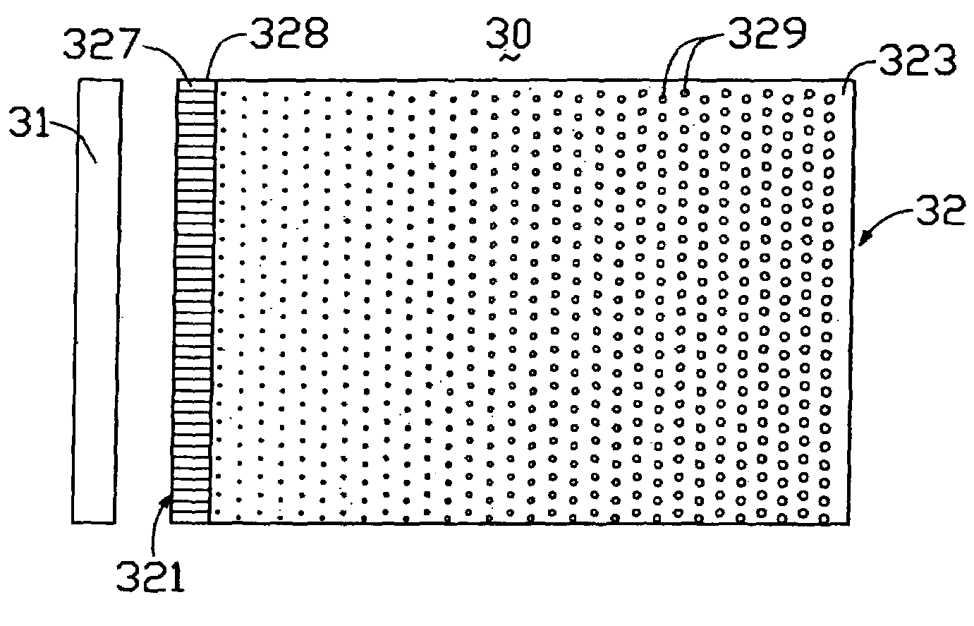
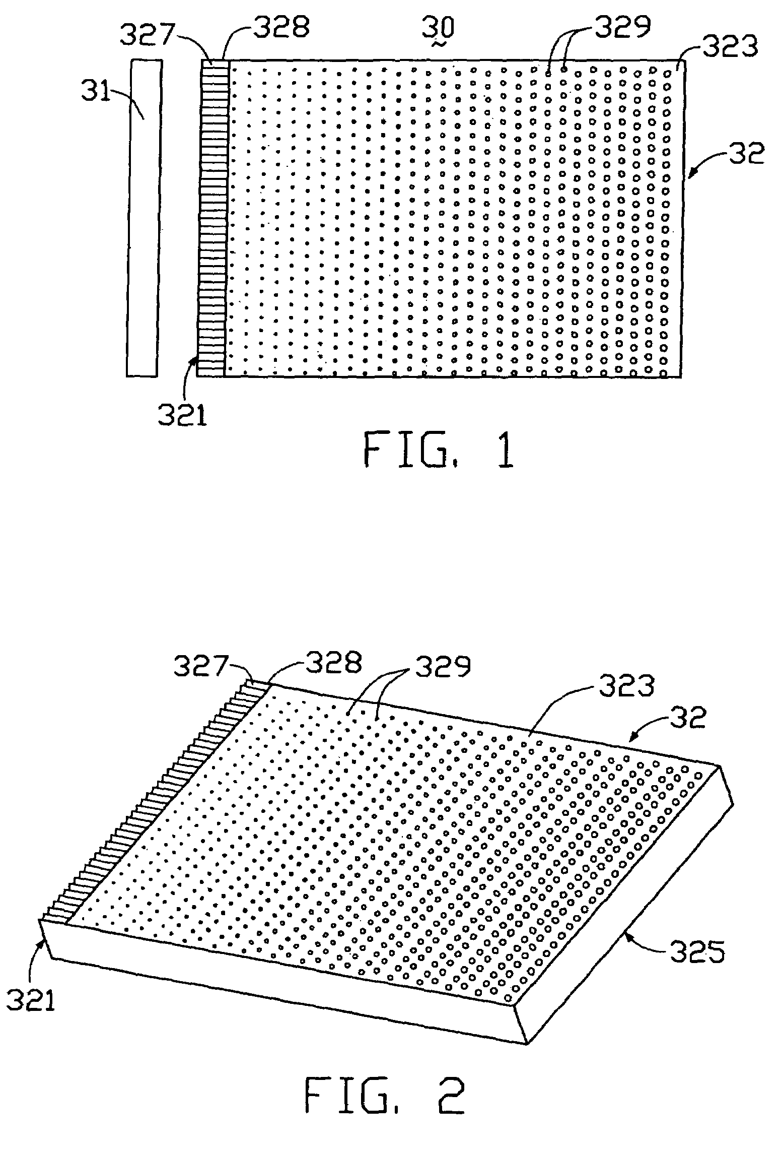
[0022]FIG. 1 shows a bottom view of a surface light source 30, which has a light source 31 and a light guide plate 32 used to transmit light from the light source 31.

[0023]FIG. 2 is a perspective view of the light guide plate 32 in FIG. 1, which is in a shape of a rectangular plate. It can instead have a shape of a wedge-plate. The thickness thereof is generally approximately 1_mm to 10 mm. The light guide plate 32 includes a light incidence surface 321, an emission surface 325 perpendicular to the light incidence surface 321, and a bottom surface 323 opposite to the emission surface 325. A groove array 328 and a plurality of reflection dots 329 are formed on the bottom surface 323, wherein the groove array 328 is adjacent to the light incidence surface 321.

[0024]In the present invention, a transparent glass or synthetic resin may be used to make the light guide plate 32. Various kinds of highly transparent synthetic resins may be used, such as acrylic resin, polycarbonate resin, vi...


PUM


Abstract

A light guide plate (32) used in a surface light source (30) for a liquid crystal display includes a light incidence surface (321) for receiving light beams, an emission surface (325) perpendicular to the light incidence surface for emitting the light, a bottom surface (323) opposite to the emission surface, and a plurality of grooves (327) and light reflection dots (329) formed on the bottom surface. The grooves are formed in a continuous band adjacent to the light incidence surface and extend perpendicular to the light incidence surface for scattering the light beams. The light guide plate provides highly uniform illumination for a liquid crystal display panel.

Description

BACKGROUND OF THE INVENTION[0001]1. Field of the Invention[0002]The present invention relates to a light guide plate and a surface light source using the same, and especially to a light guide plate providing highly uniform illumination.[0003]2. Description of Related Art[0004]Recently, color liquid crystal display devices have been widely used in various applications, such as in portable personal computers, liquid crystal display televisions, video built-in type liquid crystal televisions, etc. This kind of liquid crystal display device comprises a back light unit and a liquid crystal panel. An under-lighting system in which a light source is disposed just under the liquid crystal panel, or an edge-lighting system in which a light source is disposed on a side surface of a light guide plate, is used as the back light unit.[0005]Recently, edge-lighting systems have been more frequently used because they allow a size of the liquid crystal display device to be reduced. In the edge-light...

Claims


Application Information

Patent Timeline
IPC IPC(8): F21V7/04F21V8/00G02B6/00
CPCG02B6/0038G02B6/0061G02B6/0043G02B6/0036G02B6/0046
Inventor TSAI, KUN-JUNG
Owner HON HAI PRECISION IND CO LTD
Why Eureka
Try Eureka