Light guide plate with diffusion dots having scattering particles and surface light source unit incorporating the light guide plate

a light guide plate and diffusion dots technology, applied in waveguides, instruments, mechanical instruments, etc., can solve the problems of limited reflectivity of white pigments b>125/b>, and the inability of light guide plates b>12/b> to provide high uniform illumination and high brightness for liquid crystal display panels, so as to improve the scattering capability of diffusion dots and high reflectivity. , the effect of high uniform illumination

Inactive Publication Date: 2006-08-01
HON HAI PRECISION IND CO LTD
View PDF23 Cites 39 Cited by
  • Summary
  • Abstract
  • Description
  • Claims
  • Application Information

AI Technical Summary

Benefits of technology

[0011]To achieve the above object, the surface light source unit of the present invention includes a light source and a light guide plate. The light source is adjacent to the light guide plate for emitting light beams. The light guide plate includes a light incidence surface for receiving the light beams from the light source, an emission surface for emitting the light beams, a light reflection surface opposite to the emission surface and a plurality of diffusion dots in which contains a plurality of light scattering particles formed on the light reflection surface for scattering the light beams. The light scattering particles are made of material having high reflectivity, such as polymethyl methacrylate (PMMA), silicon dioxide (SiO2), or the like. The light scattering particles have substantially global surfaces for reflecting the light beams. The light scattering particles are dispersed into the diffusion dots during the formation of the diffusion dots. The light scattering particles improve the scattering capability of the diffusion dots, so that the surface light source unit can provide a high uniform illumination for a liquid crystal display panel.

Problems solved by technology

However, the reflectivity of the white pigment 125 is limited.
This loss of light beams means that the light guide plate 12 cannot provide high uniform illumination and high brightness for a liquid crystal display panel.

Method used


Image

  • Light guide plate with diffusion dots having scattering particles and surface light source unit incorporating the light guide plate
  • Light guide plate with diffusion dots having scattering particles and surface light source unit incorporating the light guide plate
  • Light guide plate with diffusion dots having scattering particles and surface light source unit incorporating the light guide plate

Examples


Embodiment Construction

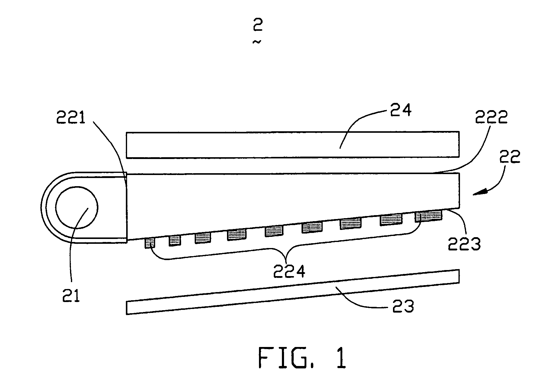
[0018]FIG. 1 shows an exploded, side elevation of a surface light source unit 2 in accordance with a preferred embodiment of the present invention. The surface light source unit 2 comprises a light source 21, a light guide plate 22, a diffusing plate 24, and a reflective plate 23.

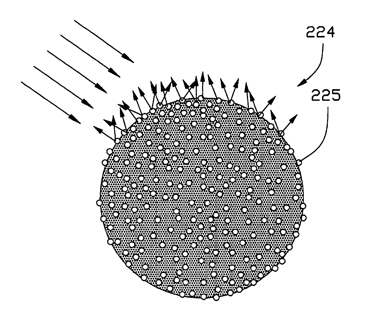
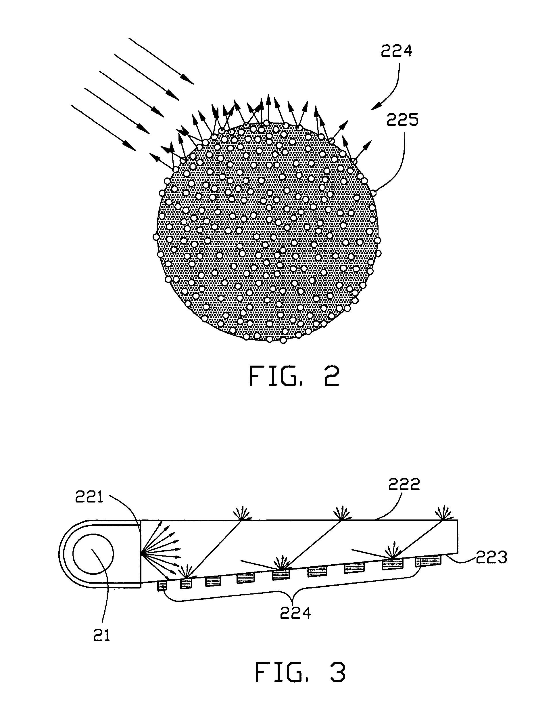
[0019]The light guide plate 22 is wedge-shaped, and includes a light incidence surface 221, an emission surface 222 and a light reflection surface 223 opposite to the emission surface 222. The light reflection surface 223 has a plurality of diffusion dots 224 formed thereon. A material of the light guide plate 22 is one that provides efficient transmission capability. The material may be an acrylic resin, such as polymethyl methacrylate (PMMA). In an alternative embodiment, a cross section of the light guide plate 22 can be rectangular.

[0020]The light source 21 is a linear light source, such as a cold cathode fluorescent lamp (CCFL). The light source 21 is disposed adjacent to the light incidence surface 22...


PUM


Abstract

A surface light source unit (2) includes a light source (21), a light guide plate (22), a reflective plate (23) and a diffusing plate (24). The light guide plate includes a light incidence surface (221) adjacent to the light source for receiving light beams, an emission surface (222) for emitting the light beams, a light reflection surface (223) opposite to the emission surface and a plurality of diffusion dots (224) formed on the light reflection surface. The diffusion dots contain a plurality of light scattering particles (225) having substantially global surfaces. The surface light source unit provides high uniform illumination for a liquid crystal display panel.

Description

BACKGROUND OF THE INVENTION[0001]1. Field of the Invention[0002]The present invention relates to a light guide plate and a surface light source unit using the same, and especially to a light guide plate providing highly uniform illumination.[0003]2. Description of Prior Art[0004]Recently, liquid crystal display devices have undergone remarkable improvements, and their market has been steadily growing. These devices save installation space by virtue of their slimness, and they can also save power.[0005]Liquid crystal displays commonly use a surface light source to provide illumination. The surface light source includes a light guide plate having a uniform thickness or being wedge-shaped. The light guide plate distributes light from a substantially linear source such as a cold cathode fluorescent lamp (CCFL), in order to provide substantially even illumination to the LCD.[0006]In particular, the light guide plate is provided for distribution of light from the light source over an area...

Claims


Application Information

Patent Timeline
Patent Type & Authority Patents(United States)
IPC IPC(8): G02B6/04F21V8/00
CPCG02B6/0043Y10S385/901
Inventor LEU, CHARLESCHEN, GA-LANELIN, MICHAELLIU, MING-HSUANYU, TAI-CHENG
Owner HON HAI PRECISION IND CO LTD
Why Eureka
Try Eureka