Microcircuit cooling for a turbine airfoil

a technology of microcircuit cooling and turbine airfoil, which is applied in the direction of machines/engines, liquid fuel engines, mechanical equipment, etc., can solve the problems of undesirable hot core gas inflow, loss of significant percentage of work imparted to the airbled from the compressor, and negative effects on the overall efficiency of the engine, so as to achieve the effect of reducing the difference in sink pressur

Inactive Publication Date: 2006-08-29
RTX CORP
View PDF9 Cites 55 Cited by
  • Summary
  • Abstract
  • Description
  • Claims
  • Application Information

AI Technical Summary

Benefits of technology

[0008]The present invention provides a microcircuit cooling system that employs a new and effective approach to cool a wall exposed to a high temperature environment that requires cooling. In an exemplary embodiment, the wall cooled is in a gas turbine engine and more particularly the wall is an airfoil wall. In particular, the present invention provides an advantage over the prior art cooling schemes in that, to achieve the same metal temperature at the wall surface, less cool compressor air is required. Less compressor bleed flow results in the additional advantage of providing an increase in turbine efficiency.
[0011]A method embodiment of the present invention is also provided for placing inlets of cooling circuits embedded within a first sidewall and a second sidewall of a coolable gas turbine airfoil. The first and second sidewalls extend longitudinally in span from a root to a tip, and extend in chord between leading and trailing edges. The sidewalls are spaced laterally apart between the leading and trailing edges and joined together by at least one partition extending longitudinally between the root and the tip to define at least two flow passages. The method comprises placing the inlets of the cooling circuits embedded within the first sidewall in flow communication with only one of the flow passages and placing the inlets of the cooling circuits embedded within the second sidewall in flow communication with at least one of the other flow passages in order to minimize the difference in sink pressures of the suction sidewall and the pressure sidewall to ensure ingestion of the coolant fluid into the inlets of the respective cooling circuits.

Problems solved by technology

A significant percentage of the work imparted to the air bled from the compressor, however, is lost during the cooling process.
The lost work does not add to the thrust of the engine and negatively effects the overall efficiency of the engine.
Too small a pressure drop across the airfoil wall can result in undesirable hot core gas in-flow.
In all cases, the minimal dwell time in the cooling aperture as well as the size of the cooling aperture makes this type of convective cooling relatively inefficient.
One cause of ineffective cooling can be found in poor film characteristics in those applications utilizing a cooling air film to cool a wall.
A person of skill in the art will recognize, however, that film cooling is difficult to establish and maintain in the turbulent environment of a gas turbine.
One of the problems associated with using apertures to establish a cooling air film is the film's sensitivity to pressure difference across the apertures.
Too great a pressure difference across an aperture will cause the air to jet out into the passing core gas rather than aid in the formation of a film of cooling air.
Too small a pressure difference will result in negligible cooling airflow through the aperture, or worse, an in-flow of hot core gas.
Both cases adversely affect film cooling effectiveness.
Another problem associated with using apertures to establish film cooling is that cooling air is dispensed from discrete points, rather than along a continuous line.
The gaps between the apertures, and areas immediately downstream of those gaps, are exposed to less cooling air than are the apertures and the spaces immediately downstream of the apertures, and are therefore more susceptible to thermal degradation.
Cooling air used to accomplish this is expensive in terms of overall fuel consumption.

Method used


Image

  • Microcircuit cooling for a turbine airfoil
  • Microcircuit cooling for a turbine airfoil
  • Microcircuit cooling for a turbine airfoil

Examples


Embodiment Construction

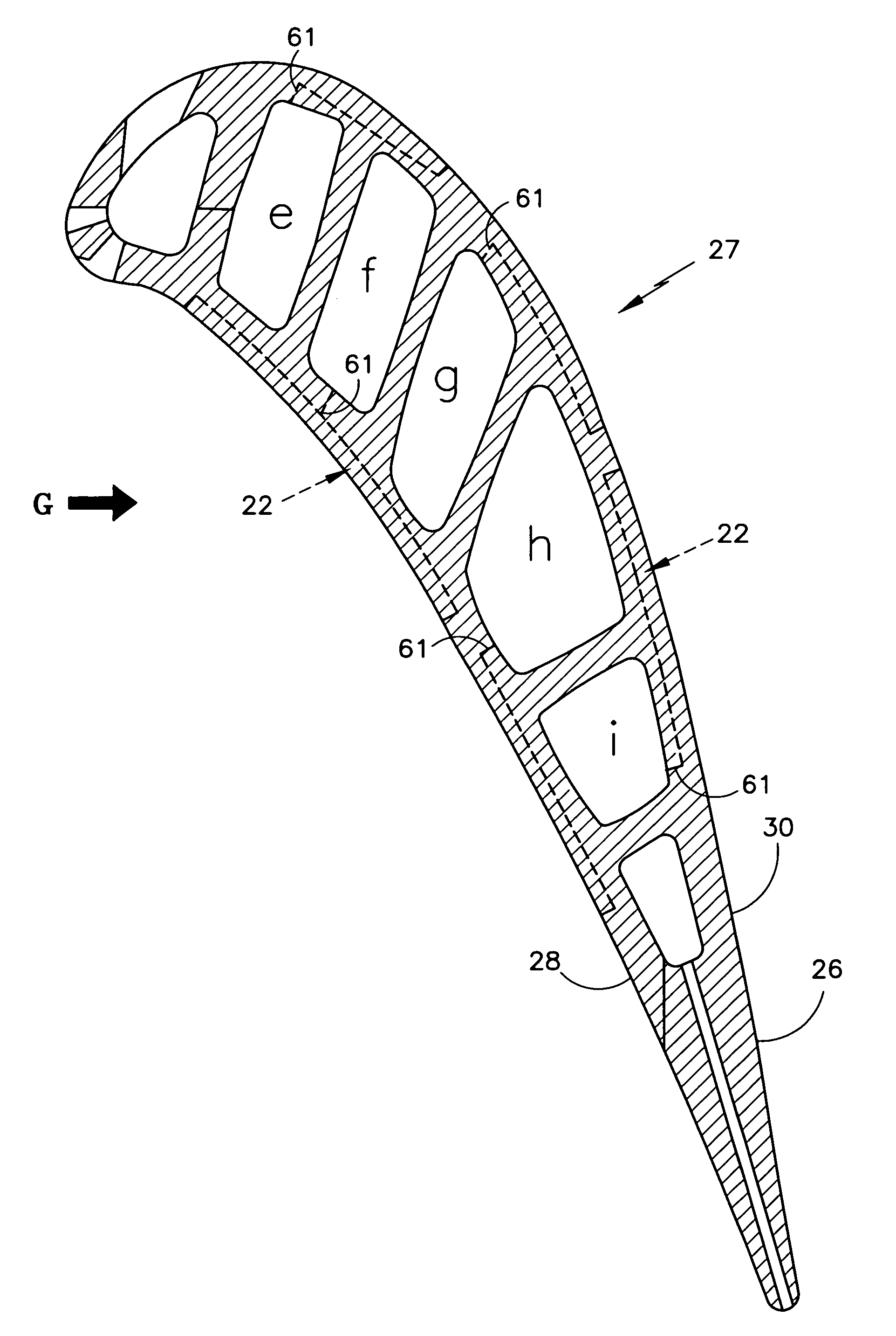
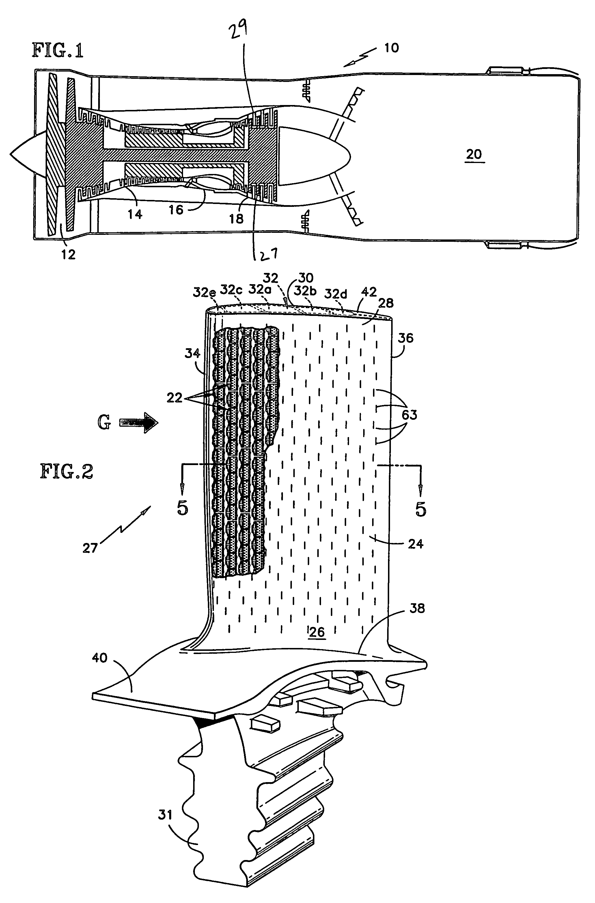
[0027]Referring to FIG. 1, a gas turbine engine 10 includes a fan 12, a compressor 14, a combustor 16, a turbine 18 and a nozzle 20. In and aft of the combustor 16, most components exposed to core gas are cooled because of the extreme high temperature of the core gas. The initial rotor stages and stator vane stages within the turbine 18, for example, are cooled using cooling air bled off the compressor 14 at a pressure higher and temperature lower than the core gas passing through the turbine 18. The turbine 18 includes alternating rows of rotary buckets or blades 27 and static vanes or nozzles 29. The use of the system of FIG. 1 is for illustrative purposes only and is not a limitation of the instant invention which may be employed on gas turbines used for electrical power generation and aircraft.

[0028]Referring to FIG. 2, a diagrammatic view of the turbine blade 27 having an airfoil 26 that includes a plurality of the present invention microcircuits (cooling circuits) 22 disposed ...


PUM


Abstract

A turbine airfoil includes a plurality of cooling circuits embedded within the pressure and suction sidewalls and a first and a second flow passage. The first flow passage feeds the coolant fluid to the cooling circuits that are embedded only within the pressure sidewall and the second flow passage feeds the coolant fluid to the cooling circuits that are embedded only within the suction sidewall. A method embodiment of the present comprises placing the inlets of the cooling circuits embedded within the first sidewall in flow communication with only one of the flow passages and placing the inlets of the cooling circuits embedded within the second sidewall in flow communication with at least one of the other flow passages to minimize the difference in sink pressures of the suction and pressure sidewalls to ensure ingestion of the coolant fluid into the inlets of the respective cooling circuits.

Description

CROSS-REFERENCE TO RELATED APPLICATIONS[0001]The present patent application is a continuation-in-part application of U.S. patent application Ser. No. 10 / 637,448 by Cunha which is entitled “Microcircuit Cooling For A Turbine Blade”, which was filed Aug. 8, 2003 now U.S. Pat. No. 6,890,154.[0002]The government may have rights in this invention, pursuant to Contract Number F33615-97-C-2279, awarded by the United States Air Force, Wright Patterson Air Force Base.BACKGROUND OF THE INVENTION[0003]This invention relates to gas turbines engines in general, and to an improved cooling scheme for airfoils.[0004]Efficiency is a primary concern in the design of any gas turbine engine. Historically, one of the principle techniques for increasing efficiency has been to increase the gas path temperatures within the engine. Using internally cooled components made from high temperature capacity alloys has accommodated the increased temperatures. Turbine stator vanes and blades, for example, are typic...

Claims


Application Information

Patent Timeline
Patent Type & Authority Patents(United States)
IPC IPC(8): F01D5/18F01D5/00F01D5/08F02C7/16F02C7/18
CPCF01D5/186F01D5/187F05D2260/22141F05D2260/2212Y02T50/676F05D2250/25Y02T50/60F01D5/18
Inventor CUNHA, FRANK J.SANTELER, KEITHGAYMAN, SCOTT W.COUCH, ERIC
Owner RTX CORP
Why Eureka
Try Eureka