Expandable element delivery system

a technology of expandable elements and delivery systems, which is applied in the direction of prosthesis, osteosynthesis devices, dental surgery, etc., can solve the problems of spinal processes and/or other spinal structures being damaged, large entry holes in the body being required to insert devices, and severe pain, so as to prevent deformation

Inactive Publication Date: 2006-08-29
KYPHON
View PDF94 Cites 535 Cited by
  • Summary
  • Abstract
  • Description
  • Claims
  • Application Information

AI Technical Summary

Benefits of technology

[0015]In a preferred embodiment of the invention, the deforming force is applied as axially as possibly with respect to the delivery system, to prevent twisting moments.
[0037]In a preferred embodiment of the invention, said force applicator and said force application mechanism are substantially restricted to a straight, narrow, elongate volume, thereby reducing moments on the force application mechanism. Alternatively or additionally, said force applicator pushes against said implant.
[0058]positioning a restraining element relative to said implant, which restraining element prevents deformation of at least some of said implant;

Problems solved by technology

Material that exits the disc may press against the spinal cord, causing severe pain.
One disadvantage of some of known fusion devices is that a relatively large entry hole in the body is required to insert the device.
Often, the spinal processes and / or other spinal structures are damaged by the insertion of the fusion device.
Another disadvantage of some known fusion devices is lies in a relative complexity of procedures for delivering the devices.

Method used


Image

  • Expandable element delivery system
  • Expandable element delivery system
  • Expandable element delivery system

Examples


embodiment

Push-Pull Embodiment

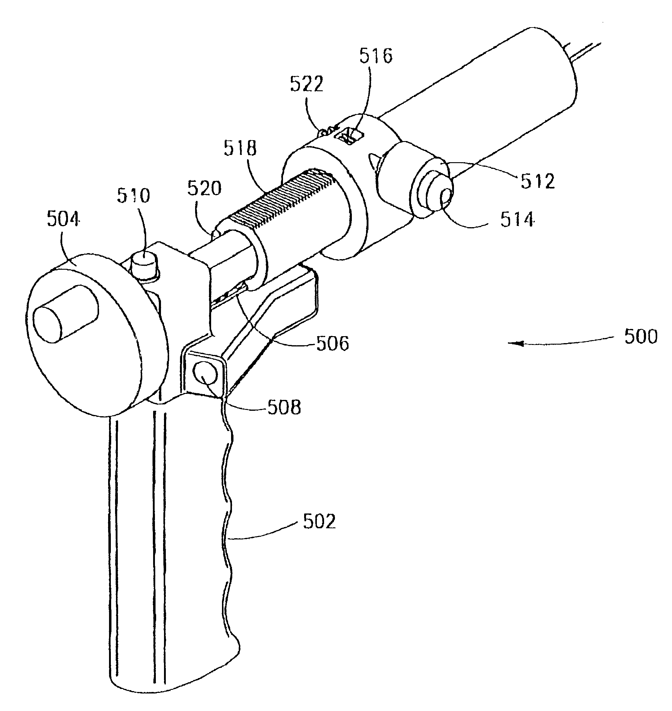
[0181]FIG. 11 illustrates an alternative eccentric-rotation based delivery system 800, in accordance with another preferred embodiment of the invention.

[0182]System 800 illustrates two features desirable in some preferred embodiments of the invention:[0183](a) advancing spacer 402 while maintaining bolt 408 in place; and[0184](b) reduction of moments in the forces applied to spacer 402.

[0185]These two features are substantially independent and one may be provided without the other.

[0186]As will be seen from FIG. 11 and the following description, forces on spacer 402, which are generally the highest forces applied during spacer deployment, are applied substantially axially, so that there is little or no twisting and / or bending moment. In some cases, forces of 30, 60 or even 100 Kg may be applied to the spacer, to expand it.

[0187]Like system 700 of FIGS. 10A and 10B, eccentric motion of a wheel is used to alternate advancing and retraction of arms. However, unlike ...


PUM

PropertyMeasurementUnit
outer diameteraaaaaaaaaa

Abstract

Apparatus for controlling the deformation of an implant during deployment thereof, comprising: a force application mechanism for applying deformation force to the implant, by motion of a force applicator against the implant; and a restraint element positioning mechanism that positions a restraining element such that the deformation of the implant is controlled by restraint of the restraining element on allowable deformation; and a synchronizer that synchronizes the motion of the restraining element and the force applicator, to achieve a desired deformation of the implanted.

Description

RELATED APPLICATIONS[0001]This application is a U.S. national filing of PCT Application No. PCT / IL00 / 00056, filed Jan. 27, 2000. This application is also related to PCT Application Nos. PCT / IL00 / 00055 and PCT / IL00 / 00058, the disclosures of which are incorporated herein by reference.FIELD OF THE INVENTION[0002]The present invention relates to delivery systems for expandable implants, and especially to delivery systems for a spinal prosthesis.BACKGROUND OF THE INVENTION[0003]A common medical situation is that of a ruptured spinal disc. Material that exits the disc may press against the spinal cord, causing severe pain. A ruptured disc is typically treated by a surgical procedure, in which the damaged disc is partially or completely removed, and spinal fusion, in which at least the two vertebrae adjacent the removed disc are fused.[0004]Disk removal may be performed percutaneously, for example via a tube through which tissue removal devices and / or an endoscope are provided.[0005]Severa...

Claims


Application Information

Patent Timeline
Patent Type & Authority Patents(United States)
IPC IPC(8): A61F2/46A61B17/56A61B17/00A61B17/02A61B17/16A61B17/22A61B17/32A61B17/58A61B17/72A61C8/00A61F2/00A61F2/02A61F2/28A61F2/30A61F2/44A61F2/48C21D1/26C21D1/34C21D1/38C22F1/00C22F1/18C22F3/00
CPCA61B17/1637A61B17/1671A61B17/22032A61B17/7266A61F2/4455A61F2/4611A61F2/4657A61B17/00234A61B2017/00261A61B2017/0256A61B2017/22034A61B2017/320004A61B2017/320008A61B2017/320048A61F2/28A61F2/30724A61F2/30744A61F2/30767A61F2/30771A61F2/3094A61F2/441A61F2/442A61F2/446A61F2002/0086A61F2002/009A61F2002/2817A61F2002/2835A61F2002/30004A61F2002/30014A61F2002/30052A61F2002/30079A61F2002/30082A61F2002/30093A61F2002/30097A61F2002/30113A61F2002/3013A61F2002/30131A61F2002/30136A61F2002/30153A61F2002/30154A61F2002/30156A61F2002/30158A61F2002/30224A61F2002/30235A61F2002/30291A61F2002/30324A61F2002/30326A61F2002/30327A61F2002/30329A61F2002/30405A61F2002/30451A61F2002/30454A61F2002/30462A61F2002/30484A61F2002/30485A61F2002/30495A61F2002/305A61F2002/30507A61F2002/3051A61F2002/3052A61F2002/30545A61F2002/30546A61F2002/3055A61F2002/30579A61F2002/30594A61F2002/30596A61F2002/30611A61F2002/30616A61F2002/30617A61F2002/30668A61F2002/3067A61F2002/30677A61F2002/30774A61F2002/30777A61F2002/30785A61F2002/30787A61F2002/30841A61F2002/30892A61F2002/30906A61F2002/3093A61F2002/30932A61F2002/30971A61F2002/4415A61F2002/4475A61F2002/448A61F2002/4485A61F2002/4619A61F2002/4623A61F2002/4627A61F2002/4635A61F2002/4638A61F2002/4649A61F2002/4658A61F2002/4677A61F2002/48A61F2210/0019A61F2210/0028A61F2210/009A61F2210/0095A61F2220/0025A61F2220/0058A61F2220/0075A61F2230/0004A61F2230/0006A61F2230/001A61F2230/0013A61F2230/0019A61F2230/0021A61F2230/0023A61F2230/0026A61F2230/0069A61F2230/0091A61F2240/001A61F2250/0001A61F2250/0002A61F2250/0007A61F2250/001A61F2250/0012A61F2250/0014A61F2250/0018A61F2250/0036A61F2250/0037A61F2250/0039A61F2250/0043A61F2250/0063A61F2250/0097A61F2310/00017A61F2310/00023Y10S606/91A61F2002/30092A61F2002/30604A61F2002/30593A61F2/4603A61F2/48A61F2/02
Inventor GLOBERMAN, ORENSHAVIT, RONENSHENHAV, BOAZ
Owner KYPHON
Why Eureka
Try Eureka