Dual cartridge air dryer with oil separator and readily changeable valves

a technology of oil separator and air dryer, which is applied in the direction of filtration separation, lighting and heating apparatus, and separation processes, etc., can solve the problems that the air brake system cannot tolerate liquid water, and the moisture in the compressed air system is well-known, and achieve the effect of economics

Active Publication Date: 2006-08-29
SKF USA INC
View PDF14 Cites 39 Cited by
  • Summary
  • Abstract
  • Description
  • Claims
  • Application Information

AI Technical Summary

Benefits of technology

[0013]Still another object of the invention is to provide an air dryer wherein the desiccant is contained in bags which are in turn contained in a cylindrical housing, which means the desiccant may be very finely subdivided for maximum effectiveness, and yet not be subject to leaking from its container.
[0016]A further object of the invention is to provide a system wherein all essential elements of the air dryers are positioned so as to be readily available for maintenance, replacement, and / or repair.
[0017]A still further object of the invention is to provide a dual cartridge dryer which achieves economy and which is adaptable to specialty equipment and a large variety of other applications.
[0018]A further object of the invention is to provide an air-oil separator having a filter medium which is surface active and which therefore adsorbs oil and moisture, and which therefore can be regenerated by drier air passing over the separator in a reverse direction.
[0020]These and other objects and advantages of the present invention are achieved in practice by providing a dual cartridge desiccator system wherein air is subjected to oil separation by a novel device used in conjunction with a well or like housing for reversing the direction of air flow, adsorbing the oil in the air stream, passing the air through a filter and through the exterior of a desiccant cartridge, and thereafter passing it down and through the desiccant cartridge, and having it exit by way of a valve to an outlet port. The other cartridge is simultaneously regenerated by a controlled amount of bleed air entering the cartridge and flowing backwards through the desiccant contained in that cartridge and ultimately out a drain port controlled by a valve opened by air pressure. This operates the cycle in an opposite direction, all without causing an interruption or a loss of air pressure to the main supply.

Problems solved by technology

The reason for having dry air is that the air brake systems do not tolerate liquid water, nor even air which is relatively high in water vapor content.
The problem of moisture in compressed air systems is well-known.

Method used


Image

  • Dual cartridge air dryer with oil separator and readily changeable valves
  • Dual cartridge air dryer with oil separator and readily changeable valves
  • Dual cartridge air dryer with oil separator and readily changeable valves

Examples


Embodiment Construction

[0032]The invention has several aspects and may be practiced in a number of different ways or with different variations. However, a description will be made of a presently preferred embodiment of the invention.

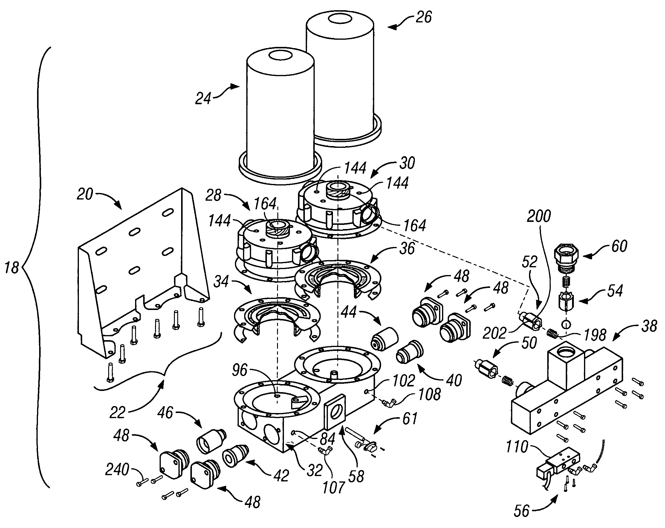
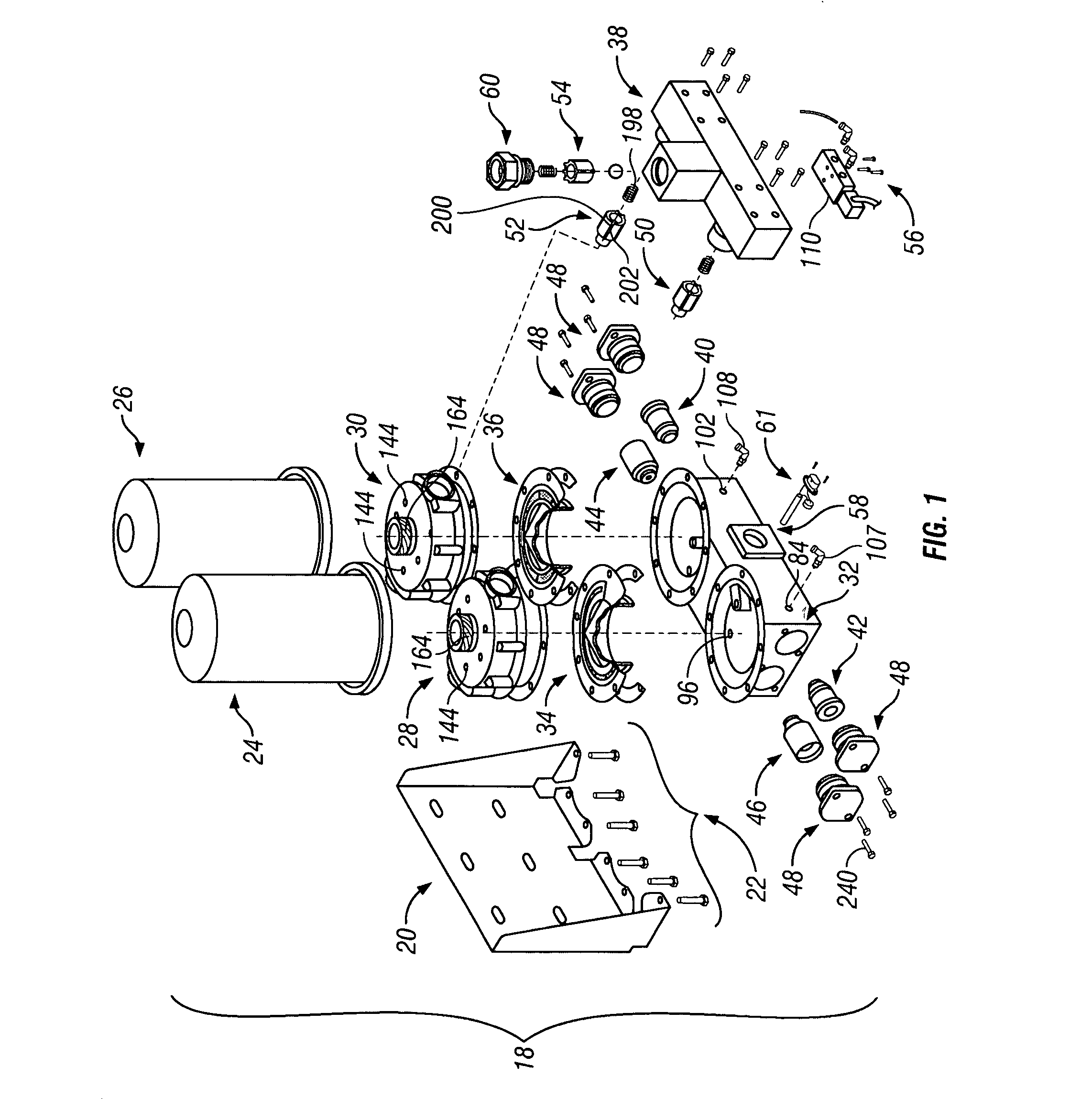
[0033]Referring now to the drawings in greater detail, FIG. 1 shows the air dryer unit generally designated 18 to include a mounting bracket generally designated 20, plural fasteners generally designated 22, and a pair of desiccant canisters generally designated 24, 26.

[0034]In addition, FIG. 1 shows a pair of annular canister mounts generally designated 28, 30, a lower valve body generally designated 32, a pair of air-oil separators generally designated 34, 36, a manifold generally designated 38 for directing a major portion of air from one cartridge to a tank or other storage facility (not shown) and for directing a minor portion of air to the other cartridge.

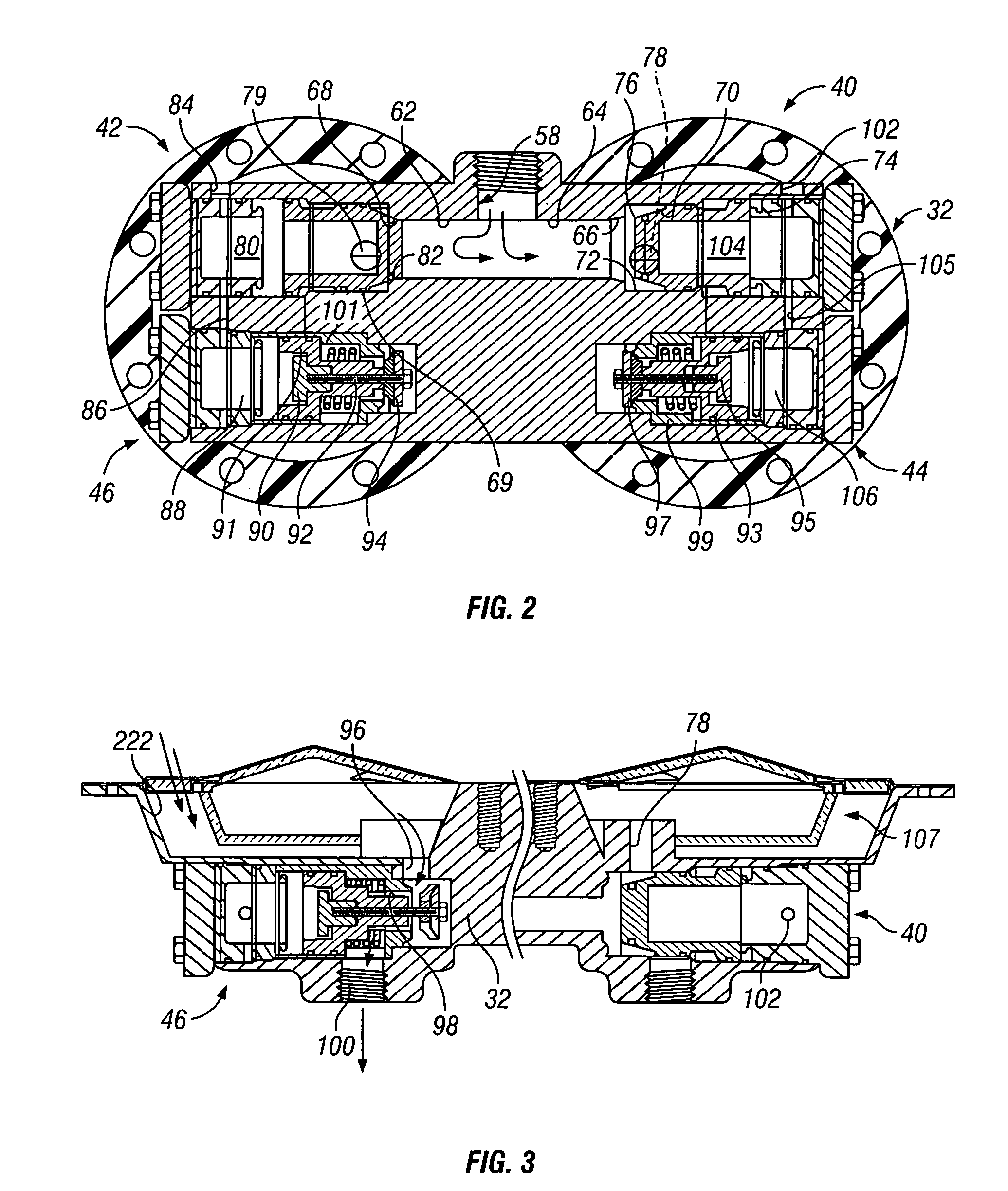
[0035]The lower valve body generally designated 32 includes a pair of inlet check valves 40, 42 and a pair of purge a...


PUM

PropertyMeasurementUnit
thickaaaaaaaaaa
pressureaaaaaaaaaa
volumeaaaaaaaaaa

Abstract

An air dryer system including two substantially identical canister-type air dryer units. Each includes a moist air inlet, a first desiccant, a dry air outlet, and means for supplying dry air to a storage facility. The system also includes a bleed valve supplying a small portion of the dry air to regenerate a second desiccant, and a first moist air purge valve. The system operates in the opposite mode and supplies air to a storage facility. Located between the moist air inlets and the desiccants are a pair of air-oil separators. In these, upwardly directed air flows through a housing, striking a deflector plate, and escapes beneath a vertically extending fence and through vents containing a filter medium.

Description

BACKGROUND OF THE INVENTION[0001]The present invention relates generally to air dryer assemblies, and more particularly to a twin tower type desiccator having two spin-on dryer cartridges each containing a volume of desiccant within a bag, and which includes a novel air-oil separator and valves which may be readily changed.[0002]The unit has particular application in buses and railroad cars, as well as other applications wherein the duty cycle of the air compressor may be continuous. Another feature of the invention is ease of maintenance, so that little if any downtime is required. This is achieved by having spin-on cartridges, accessible valves and an oil separator which may be removed and replaced easily.[0003]The unit operates, basically, by drying incoming compressed air in one cartridge while simultaneously regenerating the opposite cartridge with a portion of previously dried air. Control over the cycles is achieved with a so-called MLT (micro-logic timer) and associated valv...

Claims


Application Information

Patent Timeline
Patent Type & Authority Patents(United States)
IPC IPC(8): B01D53/04F26B21/00B01D53/02B01D53/26
CPCB01D45/08B01D46/003B01D53/0415B01D53/261B01D2257/702Y10S55/17B01D2259/40003B01D2259/40086B01D2259/402B01D2259/4566B01D2257/80B01D53/04F26B21/00
Inventor SALZMAN, MONTEMAHONEY, TOM
Owner SKF USA INC
Why Eureka
Try Eureka