Fuel vapor treatment device

a technology of fuel vapor treatment and treatment device, which is applied in the direction of combustion air/fuel air treatment, machine/engine, separation process, etc., can solve the problems of partial clogging of the filter, insufficient dust removal effect, and inability to expect a sufficient dust removal effect, etc., to achieve sufficient dust removal effect and high flow speed in the bent section

Active Publication Date: 2006-08-29
NISSAN MOTOR CO LTD +1
View PDF11 Cites 30 Cited by
  • Summary
  • Abstract
  • Description
  • Claims
  • Application Information

AI Technical Summary

Benefits of technology

[0008]It is, therefore, an object of the present invention to provide an improved fuel vapor treatment device which can effectively overcome drawbacks encountered in conventional fuel vapor treatment devices.
[0009]Another object of the present invention is to provide an improved fuel vapor treatment device which can maintain the performance of the device throughout a long time use without being affected by its install posture.
[0010]A further object of the present invention is to provide an improved fuel vapor treatment device which is configured to effectively prevent a filter used therein from being clogged with dust throughout a long time use.
[0011]A still further object of the present invention is to provide an improved vapor treatment device in which atmospheric air containing dust is subjected to its flow direction change prior to be passed to a filter, thereby separating considerable dust in atmospheric air before filtering by the filter.

Problems solved by technology

Accordingly, if the devices are installed at their lateral posture or inclined posture, a sufficient dust removing effect cannot be obtained.
However, the inside of the bent section of the passage is smaller in cross-sectional area, and therefore a flow speed in the bent section is high thereby making it impossible to expect a sufficient dust removing effect.
Consequently, dust sucked through the atmospheric air port is concentrated at the above portion of the filter, thereby causing a partial clogging of the filter.

Method used


Image

  • Fuel vapor treatment device
  • Fuel vapor treatment device
  • Fuel vapor treatment device

Examples


Embodiment Construction

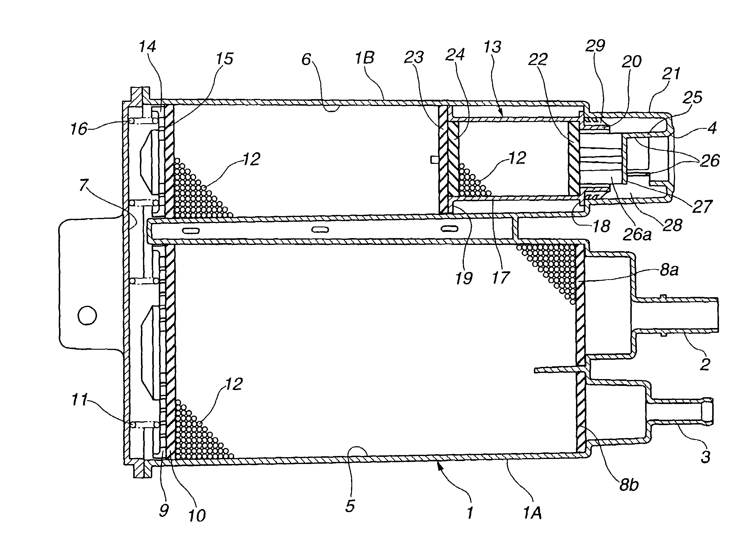
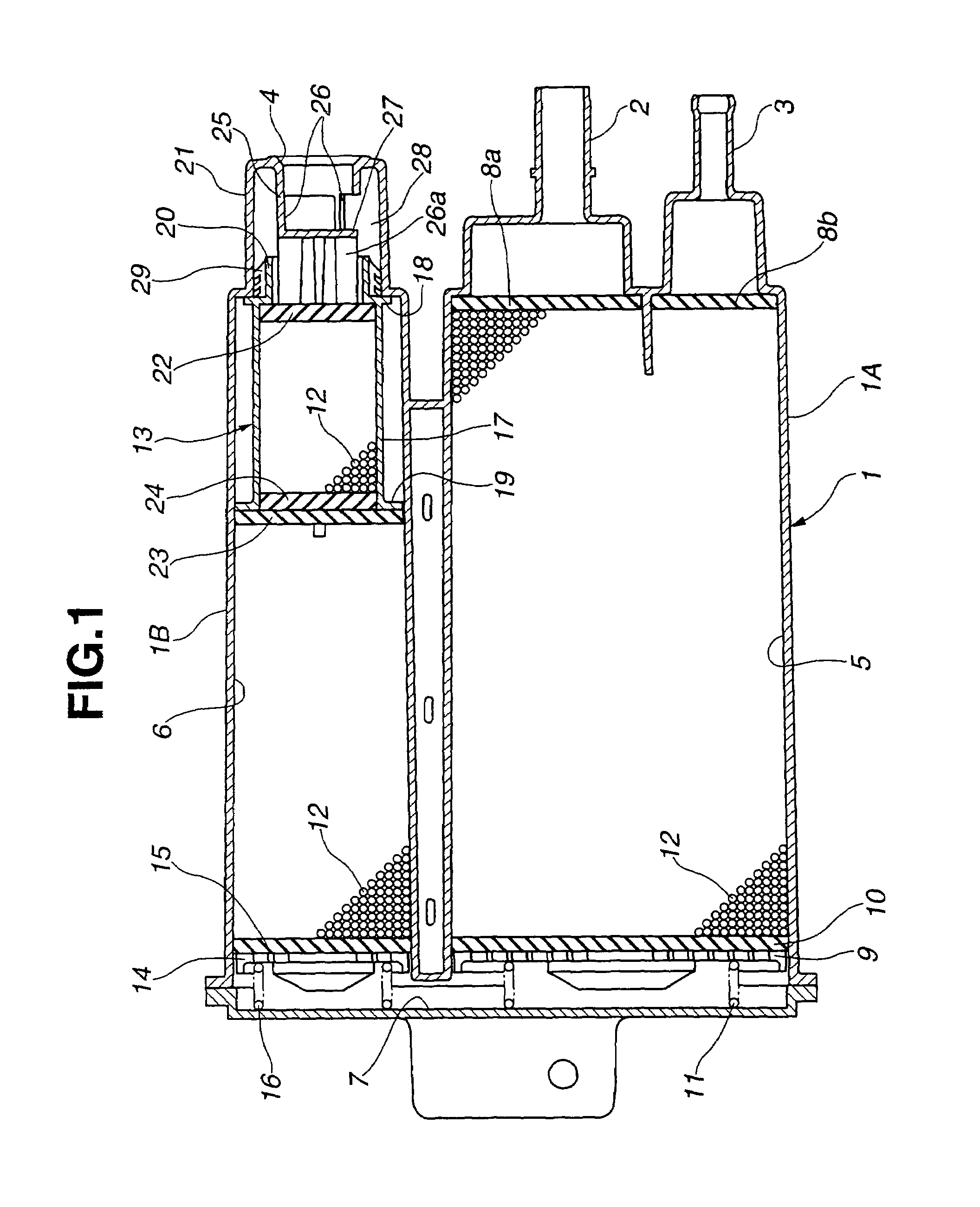
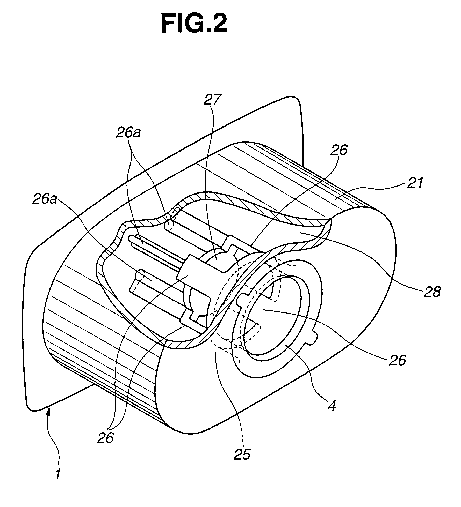
[0022]Referring now to FIGS. 1 and 2, a first embodiment of a fuel vapor treatment device according to the present invention is illustrated. The vapor treatment device comprises casing 1 formed of a resin material (synthetic resin). Casing 1 is formed at its one end side with charge port 2, purge port 3 and atmospheric air port 4. Charge port 2 is connected to a fuel tank (not shown) of an automotive vehicle. Purge port 3 is connected to an intake side or system (not shown) of an internal combustion engine (not shown) of the vehicle. Atmospheric air port 4 is communicated with atmospheric air. The inside of casing 1 is divided into first charging chamber 5 and second charging chamber 6. In other words, casing 1 includes a first casing section 1A defining therein first charging chamber 5, and a second casing section 1B defining therein second charging chamber 6. First charging chamber 5 is communicated with charge port 2 and purge port 3. Second charging chamber 6 is communicated wit...


PUM

PropertyMeasurementUnit
cross-sectional areaaaaaaaaaaa
areaaaaaaaaaaa
flow resistanceaaaaaaaaaa

Abstract

A fuel vapor treatment device for an automotive vehicle includes a casing having a charge port connected to a fuel tank, a purge port connected to an intake side of an engine, and an atmospheric air port through which atmospheric air is introduced. Fuel vapor adsorbing material is filled in the casing. A filter is disposed in the casing and between the atmospheric air port and the fuel vapor adsorbing material to trap dust contained in atmospheric air. A baffle plate is disposed in the casing and between the atmospheric air port and the filter to change flow of atmospheric air introduced through the atmospheric air port into a generally radial direction. Additionally, an annular space is formed around the baffle plate so that atmospheric air from the baffle plate flows through the annular space to the filter.

Description

BACKGROUND OF THE INVENTION[0001]This invention relates to improvements in a fuel vapor treatment device configured to adsorb fuel vapor from a fuel tank and the like of an automotive vehicle and release the adsorbed fuel to be combusted in an engine during operation of the engine.[0002]In general, a fuel vapor treatment device or canister of this type includes a casing which is formed with a charge port connected to the fuel tank, a purge port connected to an intake side of the engine, and an atmospheric air port through which atmospheric air is introduced. A fuel vapor adsorbing material such as activated carbon or the like is filled inside the casing. The adsorbing material is isolated from atmospheric air introduced from the atmospheric air port by a filter, and therefore dust contained in atmospheric air is trapped by the filter.[0003]Now, in the fuel vapor treatment device of this kind, the amount of dust trapped in the filter gradually increases with lapse of time so that the...

Claims


Application Information

Patent Timeline
Patent Type & Authority Patents(United States)
IPC IPC(8): B01D53/02F02M25/08B01D46/42B01D53/04
CPCB01D53/0431F02M25/0854B01D53/0415B01D2253/102B01D2257/702B01D2257/708B01D2259/40086B01D2259/403B01D2259/4516B01D2259/4566B01D2258/01
Inventor NAKAMURA, TSUYOSHIKAKU, SOUICHIROUMATSUSHIMA, HIDEYUKI
Owner NISSAN MOTOR CO LTD
Why Eureka
Try Eureka