Molten carbonate fuel cell

a fuel cell and carbonate technology, applied in the field of fuel cells, can solve the problems of evaporation of liquid, change of porous structure, and inability to be properly used, and achieve the effect of improving reliability and preventing the leakage of fuel gas

Active Publication Date: 2006-08-29
KOREA ELECTRIC POWER CORP
View PDF3 Cites 6 Cited by
  • Summary
  • Abstract
  • Description
  • Claims
  • Application Information

AI Technical Summary

Benefits of technology

[0018]It is an object of the present invention to provide a molten carbonate fuel cell capable of preventing the leakage of a fuel gas due to deterioration of material by suppressing a high temperature generated at a hot section within a unit cell, thereby improving the reliability thereof.

Problems solved by technology

However, since a unit cell forming one cell generates a low electromotive force of 1 V, it is no properly to be practically used.
Specifically, there are some situations: change of the porous structure, and evaporation of the liquid electrolyte, which are due to the high temperature; consumption of the electrolyte and deformation of the separator plates, which are due to the increased corrosion of the metal separator plate; and leakage of the fuel gas, due to these causes.
However, since the oversupply of the oxidant for suppressing the production of the hot section causes the high pressure to be produced within the passage, the fuel gas is leaked out due to the rupture of the wet seal, thereby significantly shortening the life of the fuel cell body.
However, the utilization of the lower current density causes the usage of the molten carbonate fuel cell to be highly limited as a power-generating plant having a high output.
When using a lot amount of oxidant gases in a long passage of oxidant gas, the leakage of the fuel gas due to the pressure generation is not evitable.
Since the oxidant gas in charge of cooling the fuel cell body flows from one surface of the stacked fuel cell to the other opposed surface, it is difficult to supply a lot amount of oxidant gases using the pressure generated by means of the long passage.

Method used


Image

  • Molten carbonate fuel cell
  • Molten carbonate fuel cell
  • Molten carbonate fuel cell

Examples


Embodiment Construction

[0028]Reference will now be made in detail to a preferred embodiment of the present invention.

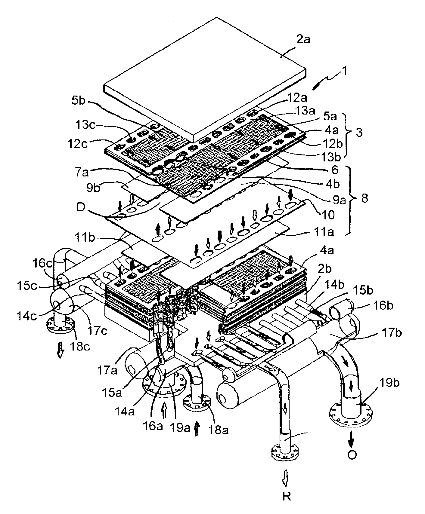
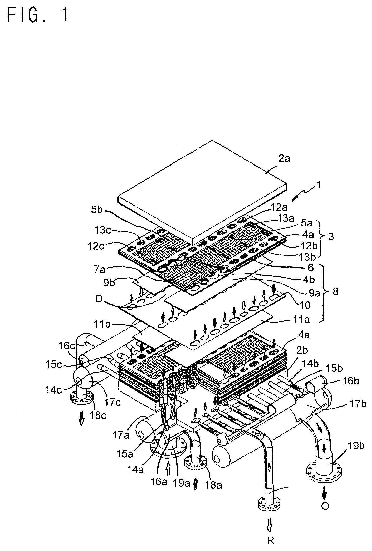
[0029]A fuel cell according to the present invention includes a plurality of stacked unit cells 8 and separator plates 3 interposed between adjacent unit cells, the respective unit cells having porous fuel electrode plates 9a and 9b, air electrode plates 11a and 11b, and electrolyte plates 10 interposed between these electrode plates. The separate plate 3 forming a body 1 of the unit cell 8 is provided with at a center thereof intake internal manifolds 12a and 13a arranged at regular intervals for taking in fuel gas R and oxidant has O towards a center of the body, and at both sides thereof exhaust internal manifolds 12b, 12c, 13b and 13c for exhausting the reacted fuel gas R and the reacted oxidant gas O, as well as forming passages for the fuel gas R and the oxidant gas O at both sides thereof.

[0030]As shown in FIG. 1, the body 1 of the fuel cell includes a plurality of stacked unit cells...


PUM

PropertyMeasurementUnit
temperatureaaaaaaaaaa
electromotive forceaaaaaaaaaa
areasaaaaaaaaaa

Abstract

Disclosed is a molten carbonate fuel cell capable of preventing the leakage of a fuel gas due to deterioration of material by suppressing a high temperature generated at a hot section within a unit cell, thereby improving the reliability thereof. The present invention provides a molten carbonate fuel cell including a plurality of stacked unit cells 8, and separator plates 3 interposed between the adjacent unit cells, the respective unit cells having porous fuel electrode plates 9a and 9b, air electrode plates 11a and 11b, and electrolyte plates 10 interposed between these electrode plates; wherein the separator plate 3 forming a body 1 of the unit cell 8 is provided with at a center thereof intake internal manifolds 12a and 13a arranged at regular intervals for taking in fuel gas R and oxidant gas O towards a center of the body, and at both sides thereof exhaust internal manifolds 12b, 12c, 13b and 13c for exhausting the reacted fuel gas R and the reacted oxidant gas O, as well as forming passages for the fuel gas R ad the oxidant gas O at both sides thereof.

Description

BACKGROUND OF THE INVENTION[0001]1. Field of the Invention[0002]The present invention relates to a fuel cell using molten carbonate as an electrolyte, and more particularly, to a molten carbonate fuel cell capable of preventing the leakage of a fuel gas due to deterioration of material by suppressing a high temperature generated at a hot section within a unit cell, thereby improving the reliability thereof.[0003]2. Background of the Prior Art[0004]A fuel cell is a power generating apparatus for converting chemical energy into electrical energy using an electrochemical reaction, and is highlighted as a new electrical energy source, because of being an environmental friendly apparatus and having a high power-generating efficiency. Such a fuel cell has a characteristic of continuously generating the power by supplying a fuel through an oxidation reaction of hydrogen and a reduction reaction of oxygen in the air.[0005]In particular, a molten carbonate fuel cell among fuel cells utilizes...

Claims


Application Information

Patent Timeline
Patent Type & Authority Patents(United States)
IPC IPC(8): H01M2/14H01M8/02H01M8/14H01M8/24
CPCH01M8/0247H01M8/142H01M8/244H01M8/0206Y02E60/526H01M2008/147H01M2300/0051H01M8/2483Y02E60/50H01M8/04H01M8/14H01M8/24
Inventor LEE, CHOONG GONKANG, BYOUNG SAMSEO, HAI KUNGLIM, HEE CHUN
Owner KOREA ELECTRIC POWER CORP
Why Eureka
Try Eureka