Carbon dioxide management in a direct methanol fuel cell system

a technology of methanol fuel cell and carbon dioxide, which is applied in the direction of cell components, cell component details, separation processes, etc., can solve the problems of power consumption, inefficiency, and bulky equipment, and achieve the effect of improving the overall efficiency of the dmfc system, avoiding bulky and power-consuming devices, and small in siz

Active Publication Date: 2006-08-29
OORJA CORP
View PDF18 Cites 6 Cited by
  • Summary
  • Abstract
  • Description
  • Claims
  • Application Information

AI Technical Summary

Benefits of technology

[0005]The present invention is a novel and elegant solution of a compact carbon dioxide separation module for a direct methanol fuel cell (DMFC). The apparatus provided by this invention is based on a more natural solution and avoids bulky and power consuming devices. In contrast to traditional solutions, the presently proposed module by itself does not draw any power; hence the module will improve the overall efficiency of a DMFC system. In addition, the module is small in size and can easily be stacked and integrated with a DMFC stack or system. The individual size of the carbon dioxide module is typically about 27 cubic inches or less.
[0009]In such a DMFC system, the integration of the carbon dioxide separation device could be further enhanced by using special holes. For instance, the exit hole of the first plate could be connected to the mixing device via a through-hole through the second plate. The integration with other plates or devices could also be accomplished via through-holes either through the first plate and / or the second plate to, for instance, connect the cathode output stream of a DMC stack to a water management device.

Problems solved by technology

For instance, one issue with traditional DMFC systems relates to the separation of carbon dioxide from the anode exhaust stream.
The traditional process of separation of carbon dioxide from the methanol and water mixture is power consuming, requires bulky equipment and quite inefficient since some of the methanol and water present in a vapor form in the anode exhaust stream are lost along with the carbon dioxide.

Method used


Image

  • Carbon dioxide management in a direct methanol fuel cell system
  • Carbon dioxide management in a direct methanol fuel cell system
  • Carbon dioxide management in a direct methanol fuel cell system

Examples


example 1

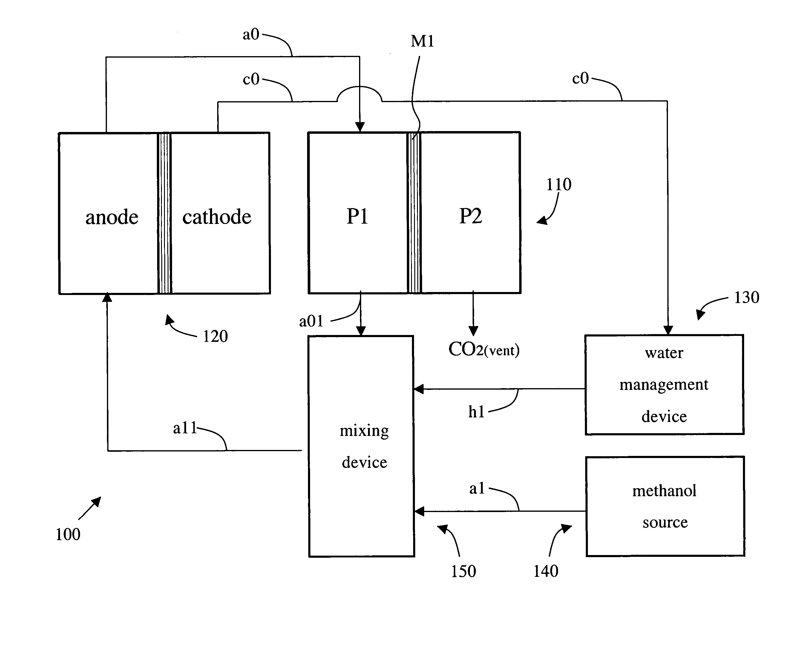
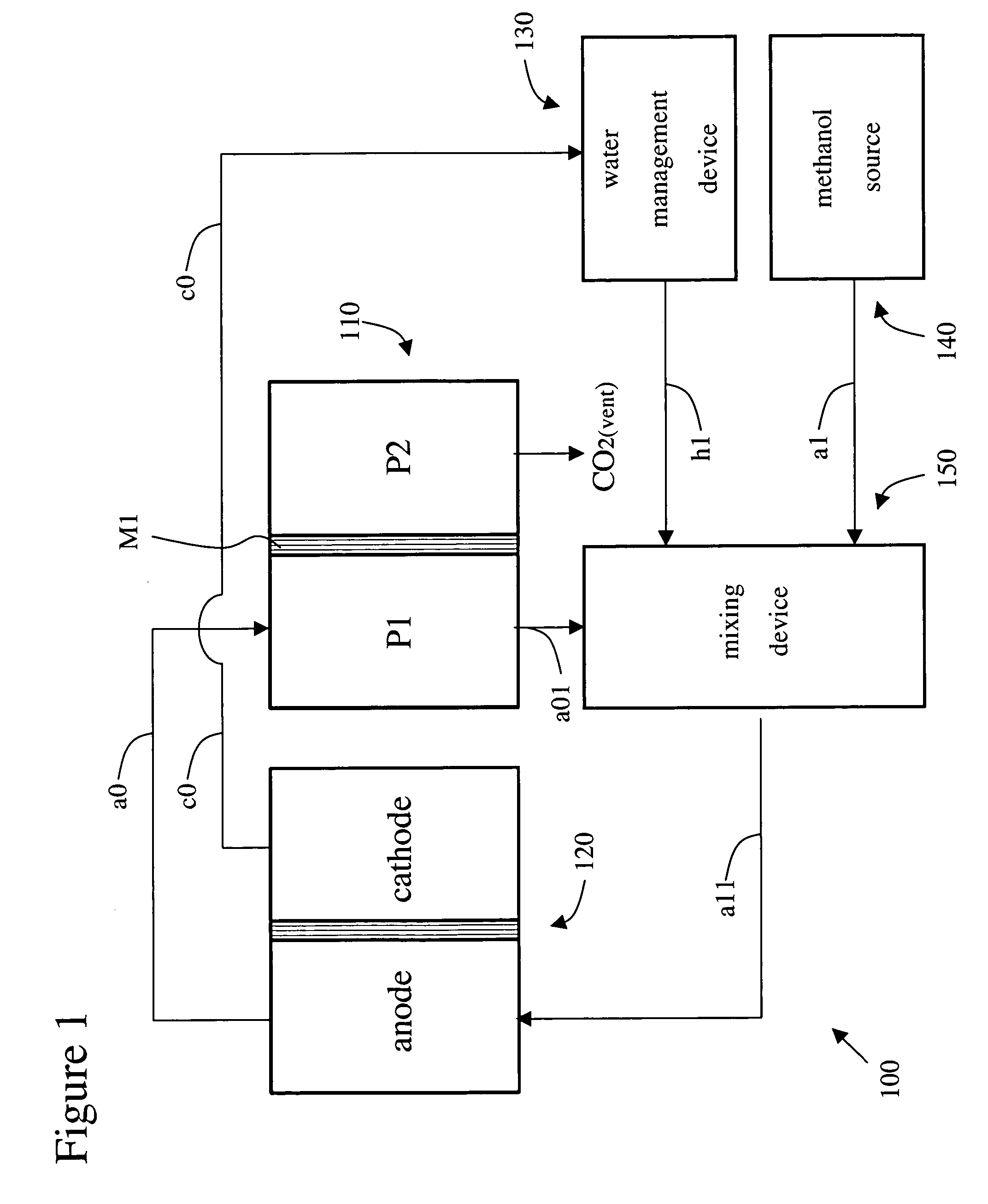
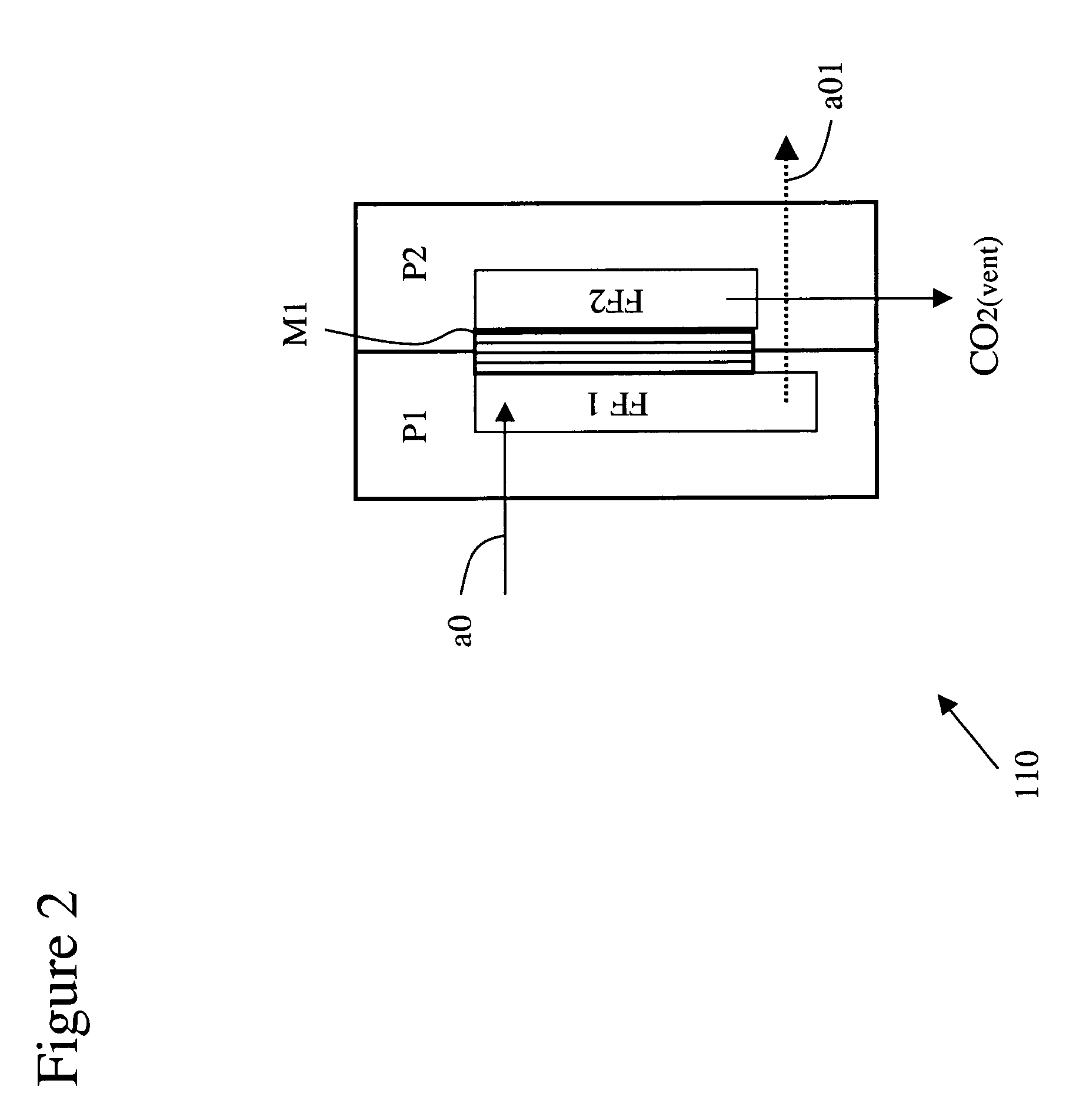
[0028]FIGS. 4–5 show an example of an approach for implementing the critical functions of water recovery from the cathode exhaust, carbon dioxide separation from the anode output stream, dilution of incoming concentrated methanol and thermal management in a direct methanol fuel cell. The individual components or modules are described without a particular preference in order. In addition, the description of the carbon dioxide separation device / module is not repeated infra and readers are referred to the description supra.

1.1 Air Supply

[0029]An air supply subsystem is added to provide the oxygen c11 to the cathode(s) to satisfy the electrochemical demand in a direct methanol fuel cell stack. The stack has an oxygen requirement in addition to the oxygen consumed by the electrochemical current producing reaction. Methanol being a small, completely water miscible molecule has a tendency to migrate from the anode side (fuel side) over to the cathode side (air side) of the cells. This cros...

example 2

[0055]FIGS. 6–7 show another example of an approach for implementing the critical functions of water recovery from the cathode exhaust, carbon dioxide separation from the anode output stream, dilution of incoming concentrated methanol and thermal management in a direct methanol fuel cell. This example is a variation of example 1 with the difference in the recovery of water related to the water management device / module. For a description of the other components or modules the reader is referred to the description supra.

2.1 Water Management

[0056]In this embodiment, cathode output stream c0 enters the flow field of plate P22 (e.g. through grooves etched or machined on the inside face of plate P22) where c0 is in contact with membrane M3. Membrane M3 performs two functions namely:[0057](i) Membrane M3 is a selective permeable membrane that permits only air to pass through it and restricts the transport of any water vapor or liquid water through it (this in contrast to membrane M2 descri...

example 3

[0075]FIGS. 8–9 show yet another example of an approach for implementing the critical functions of water recovery from the cathode exhaust, carbon dioxide separation from the anode output stream, dilution of incoming concentrated methanol and thermal management in a direct methanol fuel cell. This example incorporates aspects of examples 1 and 2. In addition, other variations are added that are described infra. For a description of the other components or modules the reader is referred to the description supra.

3.1 Variations

[0076]A first variation relates to the carbon dioxide separation module, which could be stacked with plate P31 that serves as a (passive) mixing device in a similar fashion as in example 1 and 2. In addition, at either side of this compact multi-functional module of plates P11, P12 and P31 thermal insulators TIs could be added to prevent heat loss through radiation from stream a01.

[0077]A second variation relates to the water management employing both solutions f...


PUM

PropertyMeasurementUnit
temperatureaaaaaaaaaa
pressureaaaaaaaaaa
volumeaaaaaaaaaa

Abstract

A compact carbon dioxide separation module for a direct methanol fuel cell (DMFC) is provided. The module is a set of plates, typically two plates, sandwiched together and enclosing a membrane permeable to carbon dioxide. The anode output stream of the DMFC stack feeds into one of the plates. The other plate has an exit hole to vent carbon dioxide permeated through the membrane. As such the module does not draw any power; hence the module will improve the overall efficiency of a DMFC system. In addition, the module is small in size and can easily be stacked and integrated with a DMFC stack. From a DMFC system perspective the module could also be nicely integrated and stacked with a mixing device / module, a water management device / module and a methanol source.

Description

CROSS-REFERENCE TO RELATED APPLICATIONS[0001]This application is cross-referenced to and claims priority from U.S. Provisional Application 60 / 480,148 filed Jun. 20, 2003, which is hereby incorporated by reference.FIELD OF THE INVENTION[0002]The present invention relates generally to direct methanol fuel cells. More particularly, the present invention relates to carbon dioxide management in direct methanol fuel cells.BACKGROUND[0003]A direct methanol fuel cell (DMFC), like an ordinary battery, provides dc electricity from two electrochemical reactions. These reactions occur at electrodes to which reactants are continuously fed. The negative electrode (anode) is maintained by supplying a fuel such as methanol, whereas the positive electrode (cathode) is maintained by the supply of oxygen or air. When providing current, methanol is electrochemically oxidized at the anode electro-catalyst to produce electrons, which travel through the external circuit to the cathode electro-catalyst whe...

Claims


Application Information

Patent Timeline
Patent Type & Authority Patents(United States)
IPC IPC(8): H01M2/14B01D53/22B03C3/01B03C3/38H01M2/00H01M8/04H01M8/06H01M8/10H01M8/18H01M8/24
CPCH01M8/04014H01M8/04156H01M8/04186H01M8/04194H01M8/06H01M8/0662H01M8/0668H01M8/1009H01M8/1011H01M8/2455Y02E60/523H01M8/04164H01M8/04291H01M2300/0082H01M8/04119Y02E60/50
Inventor MALHOTRA, SANJIV
Owner OORJA CORP
Why Eureka
Try Eureka