
Compact multi-functional modules for a direct methanol fuel cell system

a fuel cell and multi-functional technology, applied in the field of direct methanol fuel cells, can solve the problems of reducing the performance of the dmfc stack, requiring bulky equipment, and being power-consuming in the traditional process of carbon dioxide separation from the methanol and water mixture, so as to improve the efficiency of the dmfc system, avoid bulky and power-consuming devices, and be compact in siz

Inactive Publication Date: 2005-01-13
OORJA PROTONICS
View PDF29 Cites 17 Cited by
  • Summary
  • Abstract
  • Description
  • Claims
  • Application Information

AI Technical Summary

Benefits of technology

The present invention is a novel and elegant solution of a compact direct methanol fuel cell (DMFC) system. The present system addresses issues related to the critical functions of water recovery from the cathode exhaust, carbon dioxide separation from the anode output stream, dilution of incoming concentrated methanol and thermal management in a DMFC system. The system provided by this invention is based on a more natural solution and avoids bulky and power-consuming devices; hence improving DMFC system's efficiency by at least 25% compared to traditional condensor-based DMFC systems. In addition, the system is relatively small in size compared to these condensor-based DMFC systems mainly due to the use of modules based on plates that are nicely integrated as a DMFC system. The individual size of the system is typically reduced by about 35% or more compared to traditional condensor-based DMFC systems.

Problems solved by technology

One issue with traditional DMFC systems relates to the separation of carbon dioxide from the anode exhaust stream.
The traditional process of separation of carbon dioxide from the methanol and water mixture is power consuming, requires bulky equipment and quite inefficient since some of the methanol and water present in a vapor form in the anode exhaust stream are lost along with the carbon dioxide.
Another example of an issue with traditional DMFC systems relates to water management, which is particularly critical for a polymer electrolyte membrane (PEM) stack used for a DMFC system.
Membrane dehydration increases the membrane resistance while a dry cathode lowers the oxygen reduction activity of the platinum catalyst; both reduce DMFC stack performance.
On the other hand and more common in practice, water management problems in a DMFC stack are more often associated with excess water in the stack rather than dry out.
Excess water can interfere with the diffusion of oxygen into the catalyst layer by forming a water film around the catalyst particles (flooding).
However, such systems consume large amounts of power relative to the power produced by the DMFC stack reducing the overall efficiency.
Yet another example of an issue with traditional DMFC systems relates to the thermal management.
This traditional approach for thermal management requires voluminous equipment that consumes a significant amount of power produced at the fuel cell stack for their operation and tends to reduce the overall system efficiency and system power density.
Still another example of an issue with traditional DMFC systems is to have a commercial fuel cell system that is water autonomous, which requires neat or commercially available methanol to be the only fuel fed to the DMFC.
However, the neat methanol fuel needs to be strongly diluted in-situ in a bulky methanol-water mixing tank to reduce the methanol crossover across the membrane electrolyte due to concentration gradients.
However, this approach leads to low power density as well as huge parasitic power consumption from multiple components and sub-systems constituting the balance of plant or auxiliary systems in a DMFC.

Method used


Image

  • Compact multi-functional modules for a direct methanol fuel cell system
  • Compact multi-functional modules for a direct methanol fuel cell system
  • Compact multi-functional modules for a direct methanol fuel cell system

Examples


example 1

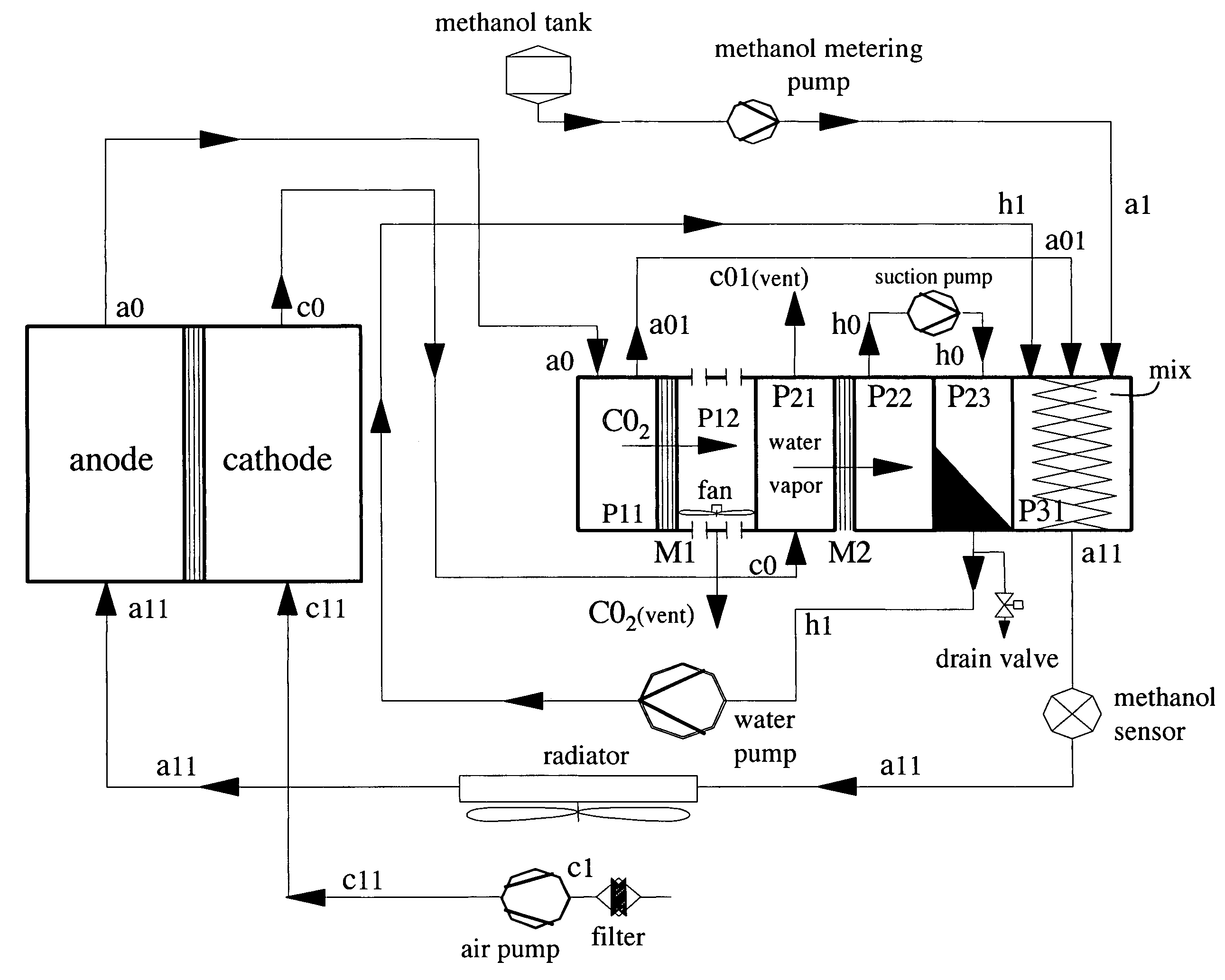
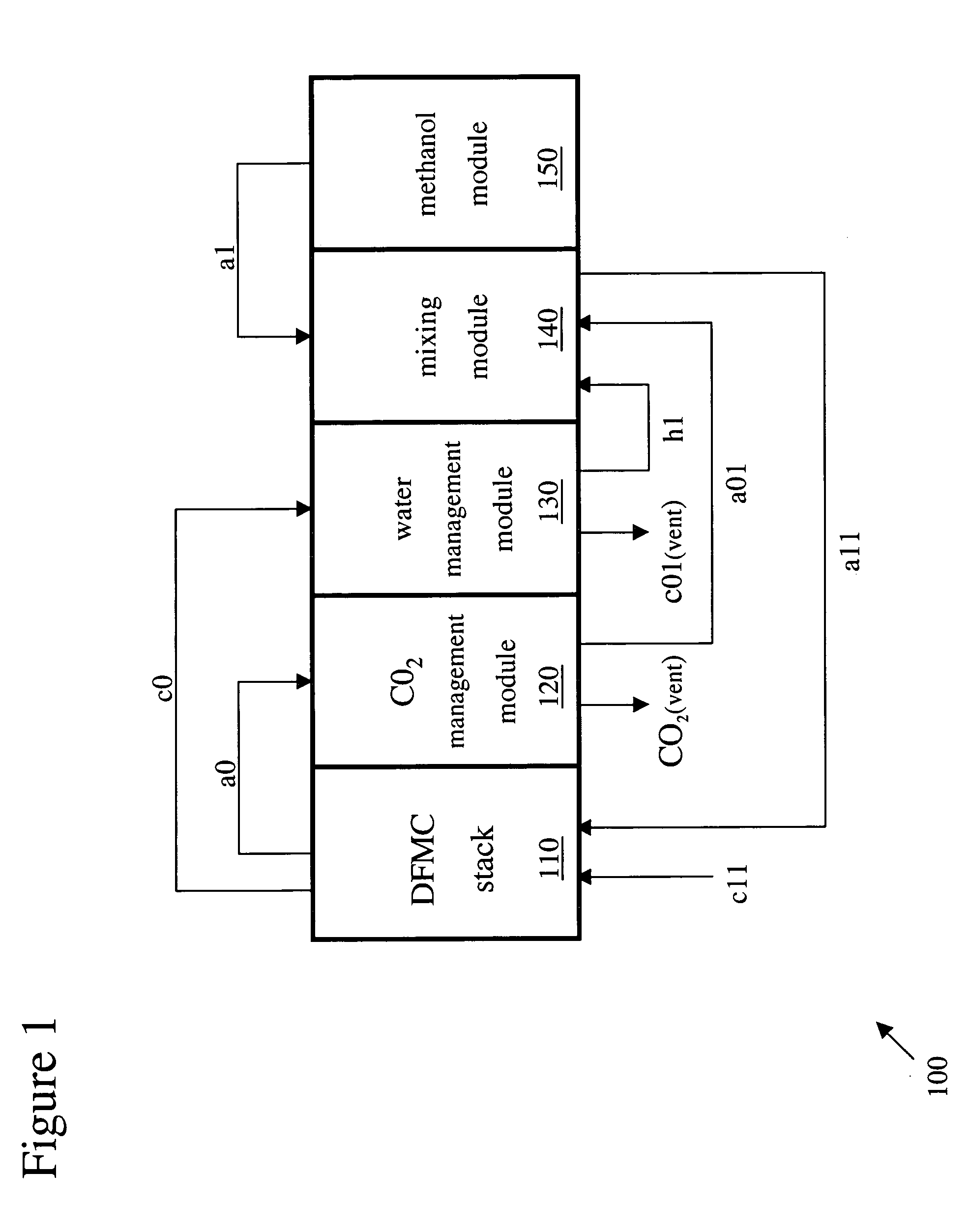
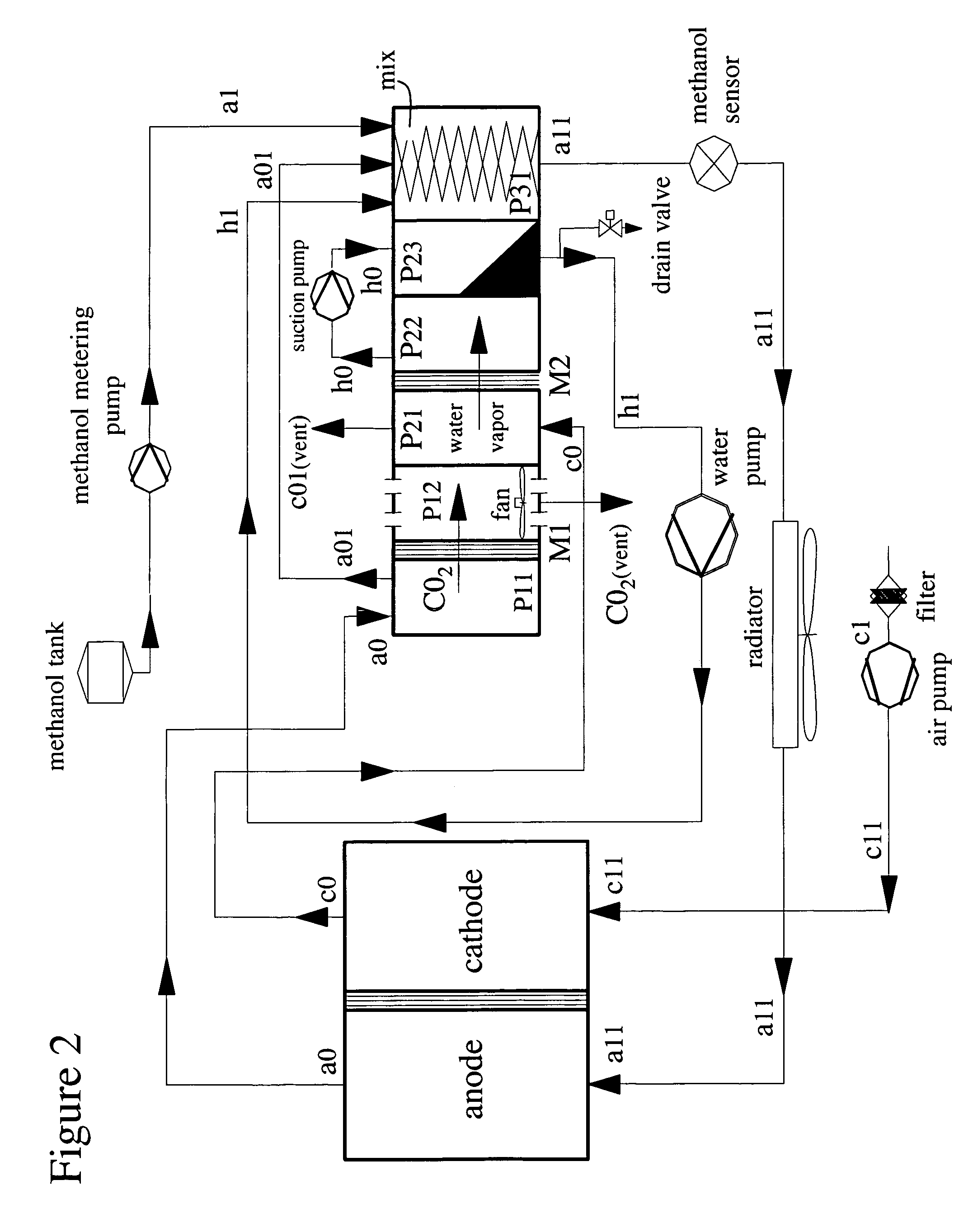
FIGS. 2-3 show an example of an approach for implementing the critical functions of water recovery from the cathode exhaust, carbon dioxide separation from the anode output stream, dilution of incoming concentrated methanol and thermal management in a DMFC system. The individual modules are described without a particular preference in order.

1.1 Carbon Dioxide Separation Module

FIGS. 2-3 show a carbon dioxide separation module with a set of plates, typically two plates P11 and P12, sandwiched together. Plates P11 and P12 enclose a membrane M1 that is permeable to carbon dioxide. Each plate, P11 and P12, has a flow field that is edged or machined to the plates. Each flow field faces and is in contact with the membrane M1. In other words, membrane M1 is a barrier between the two flow fields.

The flow field of plate P11 receives an anode output stream a0 of direct methanol fuel cell stack 120. This anode output a0 stream typically contains carbon dioxide, unused methanol and unused w...

example 2

FIGS. 4-5 show another example of an approach for implementing the critical functions of water recovery from the cathode exhaust, carbon dioxide separation from the anode output stream, dilution of incoming concentrated methanol and thermal management in a DMFC system. This example is a variation of example 1 with the difference in the recovery of water related to the water management device / module. For a description of the other components or modules the reader is referred to the description supra.

2.1 Water Management

In this embodiment, cathode output stream c0 enters the flow field of plate P22 (e.g. through grooves etched or machined on the inside face of plate P22) where c0 is in contact with membrane M3. Membrane M3 performs two functions namely: (i) Membrane M3 is a selective permeable membrane that permits only air to pass through it and restricts the transport of any water vapor or liquid water through it (this in contrast to membrane M2 described with respect to FIGS. ...

example 3

FIGS. 5-6 show yet another example of an approach for implementing the critical functions of water recovery from the cathode exhaust, carbon dioxide separation from the anode output stream, dilution of incoming concentrated methanol and thermal management in a DMFC system. This example incorporates aspects of examples 1 and 2. In addition, other variations are added that are described infra. For a description of the other components or modules the reader is referred to the description supra.

3.1 Variations

A first variation relates to the carbon dioxide separation module, which could be stacked with plate P31 that serves as a (passive) mixing device in a similar fashion as in example 1 and 2. In addition, at either side of this compact multi-functional module of plates P11, P12 and P31 thermal insulators TIs could be added to prevent heat loss through radiation from stream a01.

A second variation relates to the water management module employing both solutions from example 1 and 2...


PUM


Abstract

A compact direct methanol fuel cell (DMFC) system based on modules is provided. The system addresses issues related to the critical functions of water recovery from the cathode exhaust, carbon dioxide separation from the anode output stream, dilution of incoming concentrated methanol and thermal management in a DMFC system. The system is based on a more natural solution and avoids bulky and power-consuming devices; hence increasing DMFC system's efficiency by at least 25%, reducing DMFC system's cost and increasing DMFC system's reliability compared to traditional condensor-based DMFC systems. In addition, the system is relatively small in size compared to these condensor-based DMFC systems mainly due to the use of modules based on plates that are nicely integrated as a DMFC system. The individual size of the system is typically reduced by about 35% or more compared to traditional condensor-based DMFC systems.

Description

FIELD OF THE INVENTION The present invention relates generally to direct methanol fuel cells. More particularly, the present invention relates to a direct methanol fuel cell system using compact multi-functional modules for water management, thermal regulation, carbon dioxide separation and methanol dilution. BACKGROUND A direct methanol fuel cell (DMFC), like an ordinary battery, provides dc electricity from two electrochemical reactions. These reactions occur at electrodes to which reactants are continuously fed. The negative electrode (anode) is maintained by supplying a fuel such as methanol, whereas the positive electrode (cathode) is maintained by the supply of oxygen or air. When providing current, methanol is electrochemically oxidized at the anode electro-catalyst to produce electrons, which travel through the external circuit to the cathode electro-catalyst where they are consumed together with oxygen in a reduction reaction. The circuit is maintained within the cell by ...

Claims


Application Information

Patent Timeline
IPC IPC(8): H01M8/02H01M8/04H01M8/06H01M8/10H01M8/24
CPCH01M8/04014H01M8/04059H01M8/04156H01M8/04164H01M8/04194Y02E60/523H01M8/06H01M8/0668H01M8/0693H01M8/1011H01M8/2455H01M8/04291Y02E60/50
Inventor MALHOTRA, SANJIV
Owner OORJA PROTONICS
Learn More