Integrated coupling module

A coupling module and optical coupling technology, applied in the field of optical sensing and signal detection, can solve the problems of fiber optic gyro system and fiber optic current transformer system that cannot be miniaturized and integrated, and achieve light weight, enhanced reliability, and small size. Effect

Pending Publication Date: 2018-02-09
西安飞秒光纤技术有限公司
View PDF0 Cites 4 Cited by
  • Summary
  • Abstract
  • Description
  • Claims
  • Application Information

AI Technical Summary

Problems solved by technology

[0005] The purpose of the present invention is to solve the problem that the fiber optic gyroscope system and the fiber optic current transformer system cannot be miniaturized and integrated due to the large size of the existing coupler, and provides an integrated coupling module, including seven fiber optic collimators, A beam splitter with a transmittance ratio of 2:1, four beam splitters with a ratio of 1:1, a beam splitter coated with a total reflection film, a V-groove for fixing the collimator, and a packaging case, etc.

Method used


Image

  • Integrated coupling module
  • Integrated coupling module
  • Integrated coupling module

Examples


Embodiment 1

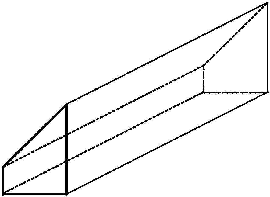
[0048] Such as image 3 and Figure 3-1 As shown, an integrated coupling module is arranged in the package shell 10, between the light source S outside the package shell and three optical path return devices, including a fiber collimator 2 and a beam splitter S1 arranged sequentially on the light path of the light source , Spectroscopic film S2 and full reflection film S3.

[0049] The integrated coupling module also includes three groups of optical coupling transmission units, each group of optical coupling transmission units includes a first optical fiber collimator, a secondary beam splitter and a second optical fiber collimator. The secondary spectroscopic sheets of the three groups of optical coupling transmission units are respectively arranged on the reflective light paths of the spectroscopic sheet S1, the spectroscopic sheet S2 and the full reflection sheet S3, and the light reflected by the spectroscopic sheet is collimated through the second optical fiber after bei...

Embodiment 2

[0058] see Figure 4 to Figure 4-3 The difference between this embodiment and Embodiment 1 is that the reflected light of the spectroscopic sheet is transmitted by the secondary spectroscopic sheet of each group of optical coupling transmission units, and then transmitted through the corresponding second optical fiber collimator and returned, and the returned light is returned again After being reflected by the second optical fiber collimator through the second optical fiber collimator, it returns to the corresponding detector through the first optical fiber collimator;

[0059] The second optical fiber collimator 4, the second optical fiber collimator 6, and the second optical fiber collimator 8 are respectively arranged on the transmission optical path of the secondary light splitter S4, the secondary light splitter S5, and the secondary light splitter S6; The collimator 3 , the first fiber collimator 5 , and the first fiber collimator 7 are respectively arranged on the opti...

Embodiment 3

[0061] see Figures 5 to 5-3 The difference between this embodiment and Embodiment 1 is that the angle between the beam splitter S1 and the beam splitter S2 and the incident direction of the light path of the light source is 45°, and the total reflection plate S30 is arranged next to the total reflection plate S3, and the total reflection plate S3 and the light source S The included angle between the incident direction is 135°, and the included angle between the full reflection film S30 and the incident direction of the light path of the light source is 45°;

[0062] The transmitted beams of the secondary beam splitter S4 and the secondary beam splitter S5 enter the second fiber collimator 4 and the second fiber collimator 6 respectively after being reflected by the total reflection plate S3; The reflection sheet S30 enters the second fiber collimator 8 after reflection.

[0063] The package size of the whole device is 30×26×6mm, and the output positions of the optical fibers...


PUM


Abstract

The invention belongs to the technical field of optical sensing and signal detection, and discloses an integrated coupling module, aiming to solve the problem that an optical fiber gyroscope system and an optical fiber current transformer system cannot be miniaturized and integrated due to the large size of the existing coupler. The integrated coupling module is set in the packaging shell, including a fiber collimator, a first beam splitter, a second beam splitter and a third beam splitter arranged in sequence on the light incident light path of the light source, and also includes respectively arranged on the first beam splitter, Three groups of optical coupling and transmission units on the reflection optical path of the second beam splitter and the third beam splitter; the optical coupling and transmission units are used to transmit the light reflected by the first beam splitter, the second beam splitter and the third beam splitter to the packaging shell The corresponding optical path foldback device outside, and transmit the folded back light to the corresponding detector; the transmittance ratio of the first beam splitter is 2:1, the transmittance of the second beam splitter is 1:1, and the third beam splitter is full negative film.

Description

technical field [0001] The invention belongs to the technical field of optical sensing and signal detection, and in particular relates to an integrated coupling module. Background technique [0002] Optical fiber coupler (Coupler), also known as splitter, is widely used in the field of optical sensing and communication to realize optical signal splitting or combining. In the existing three-axis light source sharing fiber optic gyroscope and fiber optic current transformer and other systems, a one-to-three coupler and three 1×2 or 2×2 couplers are needed to realize its functions. It is contrary to the development direction of globalization, integration and light weight. [0003] The size of the mainstream 1×3 tapered fiber coupler on the market is 1×2 tapered fiber coupler size in The advantage of this type of coupler production is that it can be produced in batches and the cost is relatively low; the disadvantage is that the operator has to try many times to determine t...

Claims


Application Information

Patent Timeline
Patent Type & Authority Applications(China)
IPC IPC(8): G02B6/42
CPCG02B6/4204G02B6/4206
Inventor 刘钊冯丽丽张丹马星袁亚飞宋龙江
Owner 西安飞秒光纤技术有限公司
Why Eureka
Try Eureka