

Low-frequency, large-power underwater sound generator
A sounder and high-power technology, which is applied in the field of low-frequency and high-power underwater sounders, can solve problems such as easy scaling and affect heat transfer efficiency and normal operation of industrial production, so as to avoid excessive volume and high temperature blowout , the effect of easy installation
- Summary
- Abstract
- Description
- Claims
- Application Information
AI Technical Summary
Problems solved by technology
Method used
Image

Examples
Embodiment 1
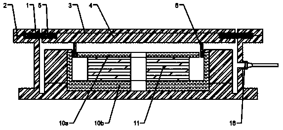
[0029] Such as figure 1As shown, the structure diagram of the low-frequency high-power underwater sounder provided by this embodiment includes a sounder housing 2, and one side of the sounder housing 2 is open, and a first diaphragm 3 and a second diaphragm are arranged at the opening. The diaphragm 4, the first diaphragm 3 and the second diaphragm 4 are closely connected, the first diaphragm 3 is arranged on the outside, and the second diaphragm 4 is arranged on the inside; the sounder housing 2 is provided with a magnetic material 11 inside, The outside of the magnetic material 11 is surrounded by the first magnetically permeable material 10a and the second magnetically permeable material 10b, and the first magnetically permeable material 10a and the second magnetically permeable material 10b are formed on the enclosing surface facing the second vibrating membrane 4. Insert one end of the voice coil 6 into the gap, and the other end of the voice coil 6 is connected to the se...
Embodiment 2
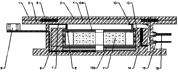
[0032] This embodiment is a further improvement on the basis of Embodiment 1, as figure 2 As shown, it also includes a cooling circulation heat exchange pipeline 7, a pressure balance pipeline 8 and an electromagnetic control valve 9, wherein the cooling circulation heat exchange pipeline 7 is wrapped around the voice coil 6, and its head and tail are connected with the electromagnetic control valve 9 to form a cooling circulation loop One end of the pressure balance pipeline 8 is arranged at the bottom end of the sounder housing 2, and the other end is connected to the electromagnetic control valve 9; the magnetic material 11 is NdFeB, which can provide good magnetic properties, and the sounder housing 2 is provided with a magnetic circuit for fixing frame 12, one end of the magnetic circuit fixing frame 12 is fixedly connected to the first magnetically conductive material 10a, and the other end is fixedly connected to the inner wall of the sounder housing 2; the second diaph...
PUM
 Abstract
Description
Claims
Application Information