
Cathode ray tube including a funnel with a non-circular shaped funnel yoke portion

Inactive Publication Date: 2006-08-29
MERIDIAN SOLAR & DISPLAY
View PDF10 Cites 2 Cited by
  • Summary
  • Abstract
  • Description
  • Claims
  • Application Information

AI Technical Summary

Benefits of technology

[0049]In order to solve the above-mentioned problem, it is an object of the present invention to provide a glass structure of a cathode ray tube which is capable of improving a deflection efficiency of a cathode ray tube, restraining BSN phenomenon occurrence and lowering a high stress acting on a funnel efficiently.

Problems solved by technology

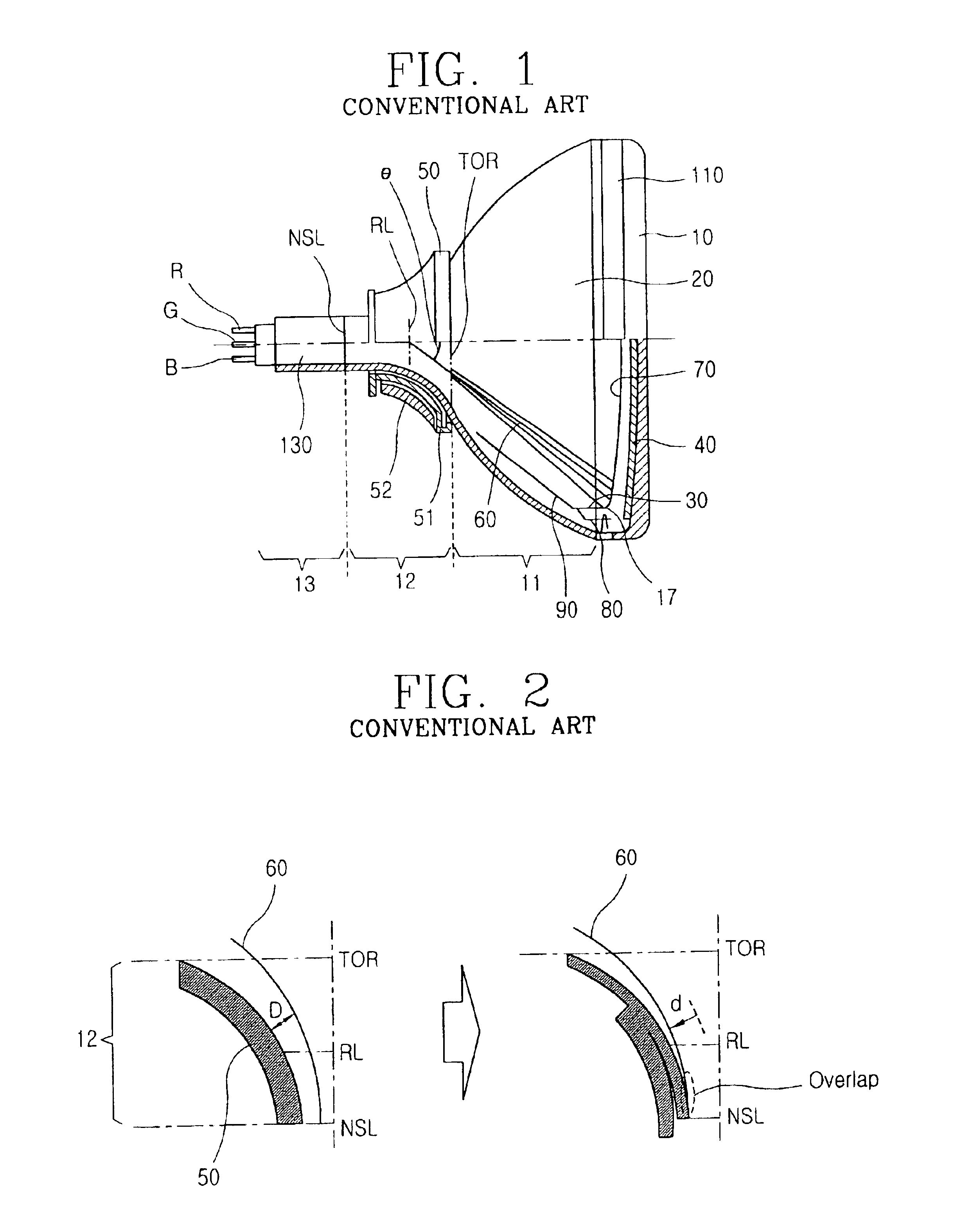
However, when the applied current is reduced, because the magnetic field generated in the core 51 is weakened, a sufficient deflection angle can not be secured, and accordingly a picture can not be formed.
In addition, when an absolute quantity of the core 51 and the coil 52 of the deflection yoke 50 is increased, a material cost and an absolute quantity of a leakage magnetic field are increased, and accordingly it is not good in the product reliability aspect.
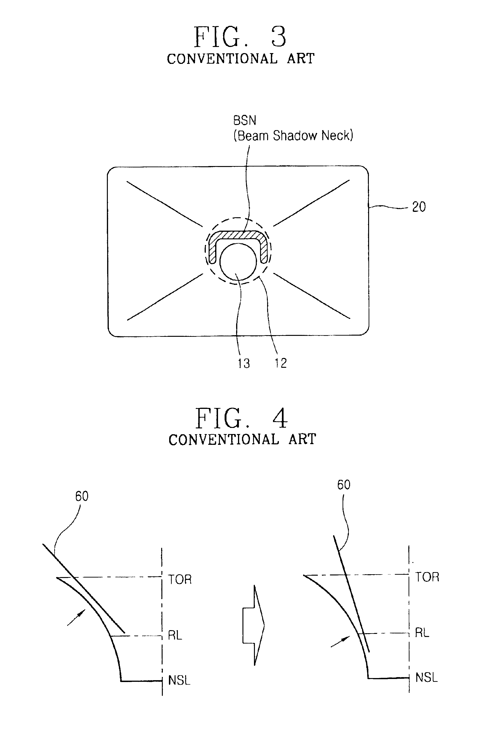
The BSN phenomenon occurrence according to the deflection efficiency increase is a major problem in slimming down the cathode ray tube and reducing a power consumption thereof.
In comparison with them, the cathode ray tube is heavy and large, and it is in a disadvantageous position in the installation facilitation, and accordingly it is required to slim down.
Herein, in the funnel 20 made of glass, the intensified stress distribution can be a fetal problem.
In that case, a shadow is thrown around the fluorescent, and it may lower the reliability of the cathode ray tube.

Method used


Image

  • Cathode ray tube including a funnel with a non-circular shaped funnel yoke portion
  • Cathode ray tube including a funnel with a non-circular shaped funnel yoke portion
  • Cathode ray tube including a funnel with a non-circular shaped funnel yoke portion

Examples


Embodiment Construction

[0071]FIG. 6 is a schematic view illustrating a reference line and a reference point for describing a glass structure of a cathode ray tube in accordance with the present invention.

[0072]A TOR (top of round) means a border line at which a yoke portion 22 of a funnel 20 of a deflection yoke meets a body portion 21 of the funnel 20.

[0073]A NSL (neck seal line) means a border line at which the yoke portion 22 of the funnel 20 meets a neck portion 23 at which an electron gun 60 is placed.

[0074]A RL (reference line) is an imaginary reference line of the funnel 20, when a cross point of a Z axis (central axis) and the RL is connected to an end 17 of a diagonal effective area of a screen as a straight line, an angle of the straight line to the Z axis is defined as a deflection angle (θ).

[0075]And, a deflection angle (θ) in FIG. 6 is ½ of an actual deflection angle.

[0076]The effective area means a region in which a picture is displayed on a screen of the panel 10 when a cathode ray tube is ...


PUM


Abstract

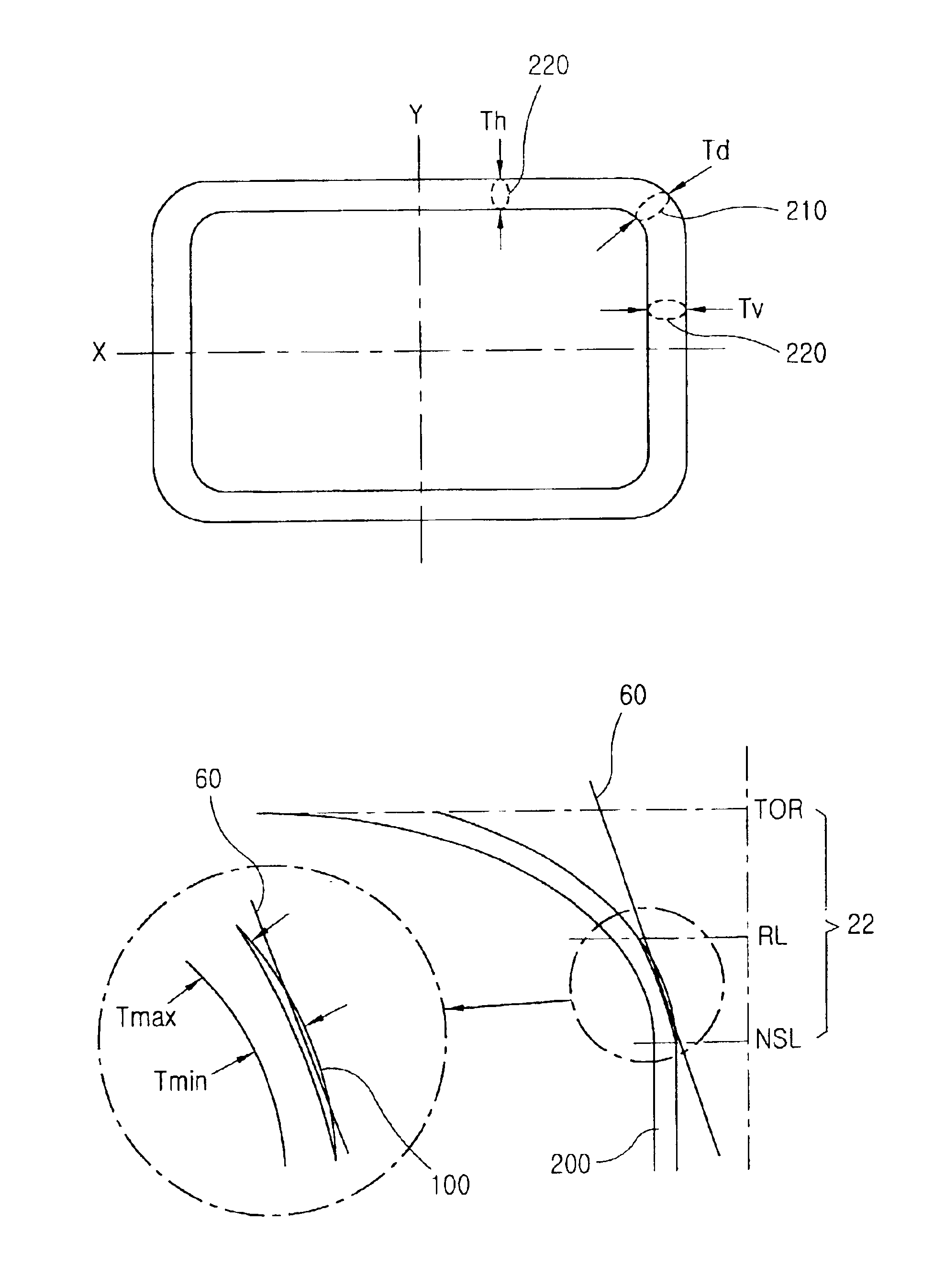
A cathode ray tube includes a panel, a funnel and a funnel yoke portion having a non-circular-shaped vertical section. When a diagonal portion thickness on a certain vertical section between a reference line and a neck line is Td and a long side portion thickness at the same vertical section is Th, a glass structure of a cathode ray tube satisfies 0.5<Th / Td<1.01. When a diagonal portion thickness at a top round is Dt′, a long side portion thickness is DS′, a short side portion thickness is DL′, a diagonal portion thickness at a reference line is Dt, a long side portion thickness is DS, and a short side portion thickness is DL, then the glass structure of a cathode ray tube satisfies 1.3≦Dt′ / Dt<1.80.

Description

BACKGROUND OF THE INVENTION[0001]1. Field of the Invention[0002]The present invention relates to a cathode ray tube, and in particular to a glass structure of a cathode ray tube which is capable of improving a deflection efficiency of a cathode ray tube, preventing a BSN phenomenon occurrence and lowering high stress acting on a funnel efficiently while improving the deflection efficiency.[0003]2. Description of the Prior Art[0004]Generally, a BSN (beam shadow neck) means a phenomenon in which a deflected electron beam clashes onto the internal surface of a yoke portion and throws a shadow on a screen.[0005]As depicted in FIG. 1, the conventional color cathode ray tube includes a R (red)•G (green)•B (blue) fluorescent 40 coated onto the internal surface, a panel 10 having an explosion-proof means at the front surface, a funnel 20 welded to the rear end of the panel 10, an electron gun 130 inserted into a neck portion of the funnel 20 and generating an electron beam 60, a deflection ...

Claims


Application Information

Patent Timeline
IPC IPC(8): H01J29/86H01J29/07H01J31/00
CPCH01J29/861H01J2229/8609H01J29/07
Inventor BAEK, JAE-SEUNGKIM, RYO-HYANG
Owner MERIDIAN SOLAR & DISPLAY
Learn More