
Deflection device for projection tube and projection tube apparatus

a technology of projection tube and deflection device, which is applied in the direction of instruments, television systems, and details scanning of television systems, can solve the problems of insufficient power consumption reduction effect, low deflection efficiency, and increase power consumption, so as to reduce the change in the shape of the beam spot, improve the deflection efficiency, and efficiently correct the pincushion distortion in the upper.

Inactive Publication Date: 2007-06-05
MATSUSHITA TOSHIBA PICTURE DISPLAY CO LTD
View PDF2 Cites 0 Cited by
  • Summary
  • Abstract
  • Description
  • Claims
  • Application Information

AI Technical Summary

Benefits of technology

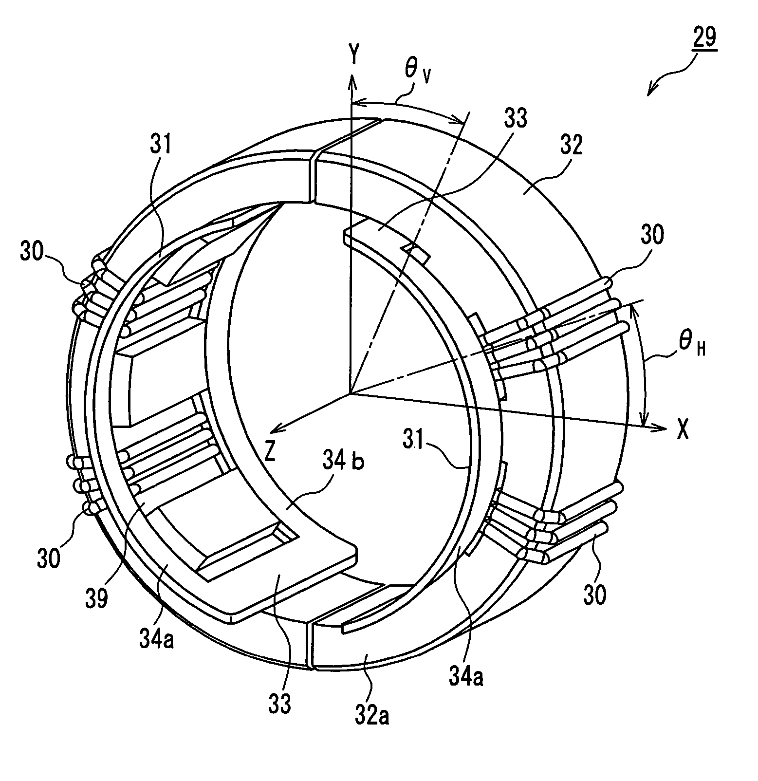
"The present invention provides a deflection device for a projection tube that improves deflection efficiency and corrects pincushion distortion while reducing changes in beam spot shape. The device includes a main deflection device for generating a raster and an auxiliary deflection device for correcting convergence. The auxiliary horizontal coil is a toroidal coil and the auxiliary vertical coil is a saddle-type coil. The projection tube apparatus includes the deflection device. The technical effects of the invention are improved image quality and reduced distortion in the upper and lower portions of the image."

Problems solved by technology

Thus, in order to correct a convergence appropriately, a high voltage for canceling the induced voltage Vt is required as a driving voltage for the auxiliary deflection device, which increases power consumption.
Therefore, a magnetic field generated from a winding present outside with respect to the auxiliary core 10 becomes a leakage magnetic field 14 that does not contribute to the deflection, resulting in a low deflection efficiency.
In the above-mentioned deflection device of JP 2002-330446 A in which both of the auxiliary horizontal coil 15 and the auxiliary vertical coil 16 are of a saddle type, although the power consumption can be reduced by decreasing an induced voltage caused by a main deflection magnetic field generated by the main deflection coil, compared with the deflection device in which both of the auxiliary horizontal coil 11 and the auxiliary vertical coil 12 are of a toroidal type, there is a problem that the effect of the reduction in power consumption is not sufficient.

Method used


Image

  • Deflection device for projection tube and projection tube apparatus
  • Deflection device for projection tube and projection tube apparatus
  • Deflection device for projection tube and projection tube apparatus

Examples


embodiment 1

[0046]First, one embodiment of the projection tube apparatus of the present invention will be described with reference to FIG. 11. As shown in FIG. 11, a projection tube apparatus 51 of the present embodiment includes a vacuum envelope composed of a glass panel 44 with a substantially rectangular screen display portion 42, a glass funnel 45 in a funnel shape connected to the panel 44, and a neck portion 46 made of glass in a cylindrical shape connected to the funnel 45. On an outer circumferential surface of the envelope extending from the neck portion 46 to the funnel 45, a deflection device 24 is mounted. The funnel 45 has a small-diameter portion (so-called yoke portion 47) extending from a connected position with respect to the neck portion 46 through a region where the deflection device 24 is mounted. In the neck portion 46, an electron gun 49 for emitting an electron beam 48 is provided. The electron beam 48 is deflected in horizontal and vertical directions by horizontal and ...


PUM


Abstract

A deflection device for a projection tube includes a main deflection device for generating a raster and an auxiliary deflection device for correcting a convergence. The auxiliary deflection device includes a toroidal auxiliary horizontal coil, a saddle-type auxiliary vertical coil, and a ferrite core. According to this configuration, the deflection efficiency is enhanced, and pincushion distortion in upper and lower portions can be corrected efficiently while a change in the shape of a beam spot is reduced.

Description

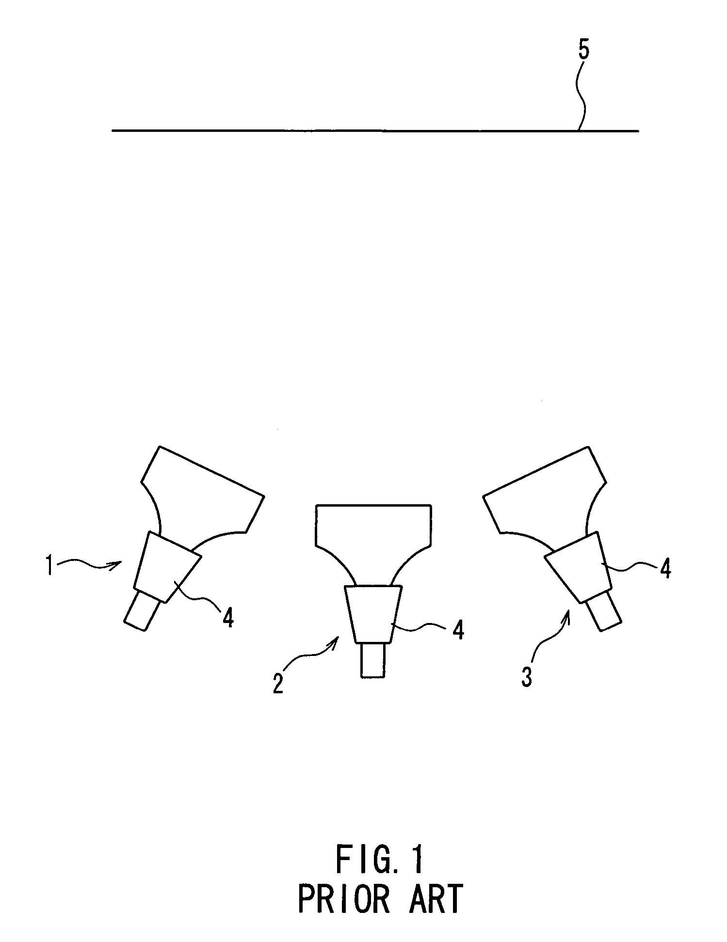
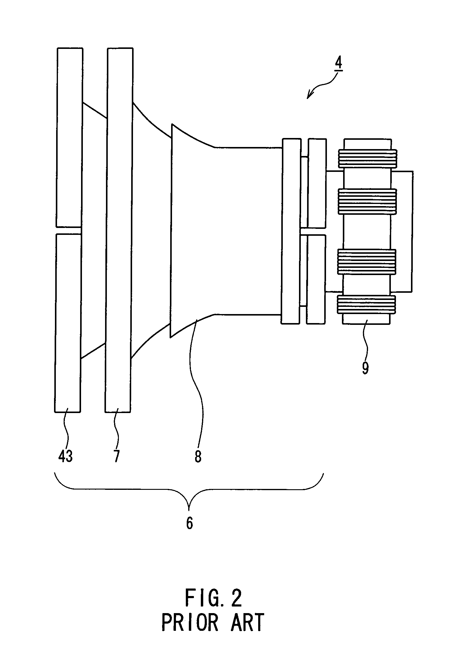
BACKGROUND OF THE INVENTION[0001]1. Field of the Invention[0002]The present invention relates to a deflection device for a projection tube, and a projection tube apparatus provided with the deflection device.[0003]2. Description of the Related Art[0004]Recently, in order to satisfy market demands for the enlargement of a screen and the reduction in price, a projection TV is being used widely. FIG. 1 is a schematic view showing a configuration of the projection TV. The projection TV includes projection tube apparatuses 1 to 3 corresponding to respective colors of red, green, and blue, and the projection tube apparatuses 1 to 3 respectively are provided with a deflection device 4. Rasters generated from the projection tube apparatuses 1 to 3 of the respective colors are projected onto a screen 5, whereby a color image is formed.[0005]FIG. 2 is a side view of the deflection device 4 provided on each of the projection tube apparatuses 1 to 3 used for the projection TV. A main deflection...

Claims


Application Information

Patent Timeline
Patent Type & Authority Patents(United States)
IPC IPC(8): H01J29/70G09G1/04H01J29/76H04N3/16H04N9/28
CPCH04N5/68H04N5/7408G09G1/04H04N9/28
Inventor YOSHINAGA, TAKAHIKO
Owner MATSUSHITA TOSHIBA PICTURE DISPLAY CO LTD
Learn More