Oscillator with variable reference

Active Publication Date: 2006-08-29
SILICON LAB INC
View PDF41 Cites 44 Cited by
  • Summary
  • Abstract
  • Description
  • Claims
  • Application Information

AI Technical Summary

Benefits of technology

[0013]As a result of providing two feedback circuits in the oscillator with variable reference, the output amplitude of the output is held constant even if changes occur in a gain of a signal path through the signal processing circuitry. Small variations in the gain of the signal path caused by, for example, process variations, operating temperature changes, and/or power supply voltage fluctuations, accumulate and result in large variation at the output. Regulating the amplitude of the initia

Problems solved by technology

Small variations in the gain of the signal path caused by, for example, process variations, operating temperat

Method used


Image

  • Oscillator with variable reference
  • Oscillator with variable reference
  • Oscillator with variable reference

Examples


Embodiment Construction

[0023]The embodiments discussed herein are illustrative of one example of the present invention. As embodiments of the present invention are described with reference to illustrations, various modifications or adaptations of the methods and / or specific structures described may become apparent to those skilled in the art. All such modifications, adaptations, or variations that rely upon the teachings of the present invention, and through which these teachings have advanced the art, are considered to be within the spirit and scope of the present invention. Hence, these descriptions and drawings should not be considered in a limiting sense, as it is understood that the present invention is in no way limited to only the embodiments illustrated.

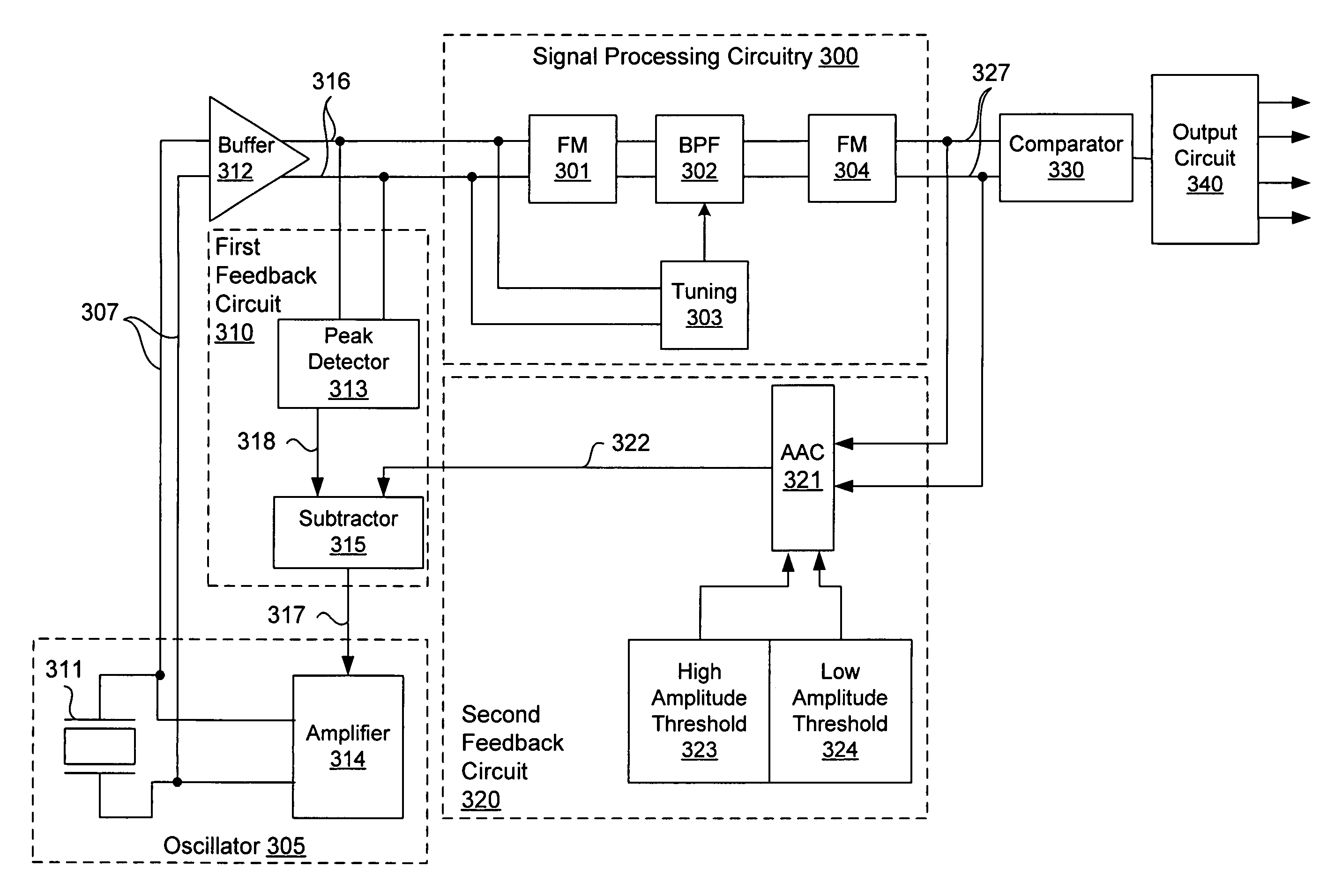
[0024]FIG. 3A illustrates a block diagram of an oscillator with variable reference in one embodiment of the invention. An oscillator 305 comprises a resonator 311 and an amplifier 314 to generate an oscillation signal 307. The oscillator 305 includ...


PUM


Abstract

A circuit for varying an amplitude of an oscillation signal comprises an oscillator, signal processing circuitry, a first feedback circuit, and a second feedback circuit. The oscillator generates the oscillation signal and has a control input to vary the amplitude of the oscillation signal. The signal processing circuitry processes the oscillation signal. The first feedback circuit is configured to control the control input of the oscillator by comparing a reference value and an input amplitude of an input of the signal processing circuitry. The second feedback circuit generates the reference value by comparing an output amplitude of an output of the signal processing circuitry and a predetermined value.

Description

CROSS-REFERENCE TO RELATED APPLICATIONS[0001]This application hereby incorporates by reference U.S. Provisional Patent Application No. 60 / 478,628, filed Jun. 13, 2003, entitled “A Semiconductor Integrated Circuit for Frequency Multiplication”. This application is also related to co-pending U.S. patent application Ser. No. 10 / 857,054 entitled “Systems and Methods for Generating an Output Oscillation Signal with Low Jitter,” filed May 28, 2004, which is hereby incorporated by reference. This application is also related to co-pending U.S. patent application Ser. No. 10 / 857,241, entitled “Tunable Differential Crystal Oscillator,” filed May 28, 2004, which is hereby incorporated by reference.BACKGROUND OF THE INVENTION[0002]1. Field of the Invention[0003]This invention relates generally to oscillators and more specifically to oscillators with variable reference.[0004]2. Description of the Background Art[0005]For signal processing circuitry to operate linearly and optimally process an ana...

Claims


Application Information

Patent Timeline
IPC IPC(8): H03B1/00
CPCH03B5/368H03L5/00H03B2200/0098H03B2200/0066
Inventor DUMITRESCU, GABRIEL-GHEORGHEOPRIS, JON E.
Owner SILICON LAB INC
Why Eureka
Try Eureka