Rotor blade for a wind turbine and wind turbine

Active Publication Date: 2021-07-22
WOBBEN PROPERTIES GMBH
View PDF18 Cites 0 Cited by
  • Summary
  • Abstract
  • Description
  • Claims
  • Application Information

AI Technical Summary

Benefits of technology

[0007]One or more embodiments are directed to a rotor blade which is characterized by compensation for lar

Problems solved by technology

Over the rotor blade, the effects of the changes to these parameters are non-uniform in this case.
Small-scale incident-flow turbulence and changes in the air density, for exa

Method used


Image

  • Rotor blade for a wind turbine and wind turbine
  • Rotor blade for a wind turbine and wind turbine
  • Rotor blade for a wind turbine and wind turbine

Examples


Embodiment Construction

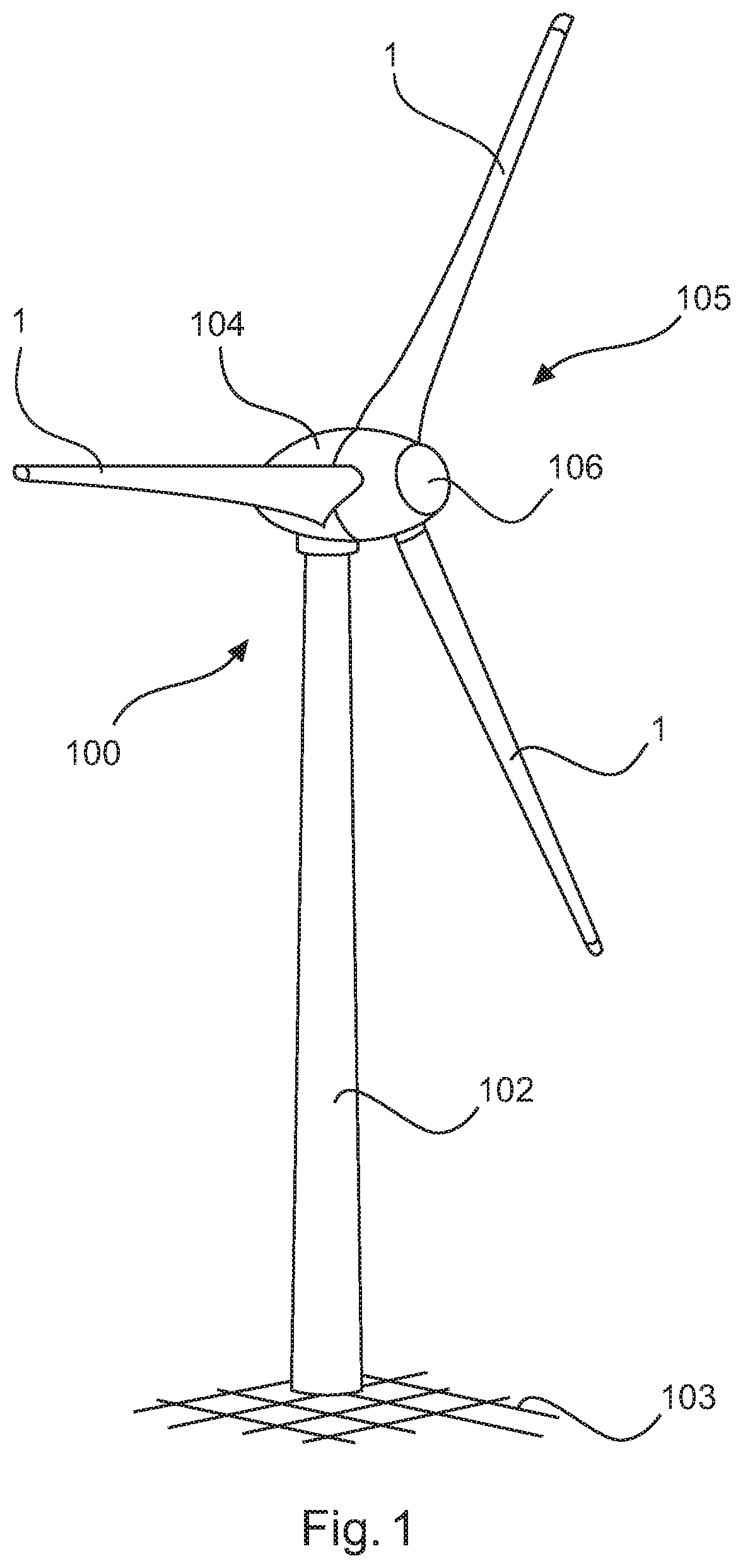
[0035]FIG. 1 shows a wind turbine 100 having a tower 102 which is erected on a foundation 103. At the upper end situated opposite the foundation 103, there is situated a nacelle 104 (machine housing) with a rotor 105, which has a rotor hub 106 and rotor blades 1 attached thereto, which rotor blades are described in more detail with reference to the further figures. The rotor 105 is coupled to an electrical generator in the interior of the nacelle 104 for the purpose of converting mechanical work into electrical energy. The nacelle 104 is mounted rotatably on the tower 102, whose foundation 103 provides the required stability.

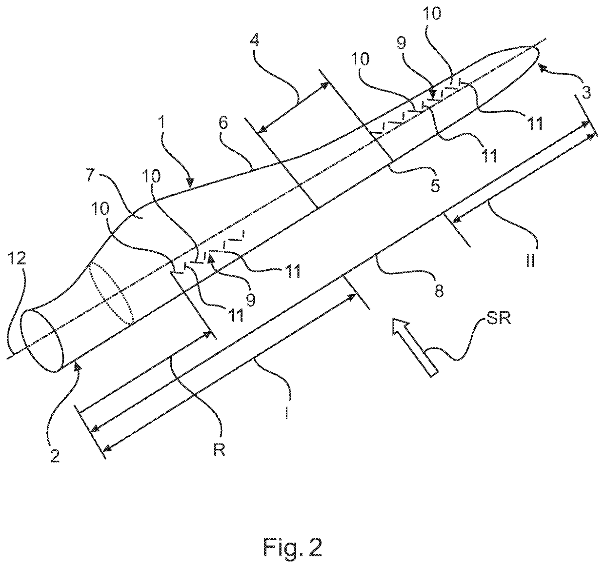
[0036]FIG. 2 shows a schematic illustration of a rotor blade 1 of an embodiment. The rotor blade 1 has at one end the rotor blade root 2 and at the end facing away therefrom a rotor blade tip 3. At the rotor blade root 2, or in general in the region near the rotor blade root 2, the rotor blade 1 has a large profile depth. At the rotor tip 3, the profile depth is...


PUM


Abstract

A rotor blade, with a suction side and a pressure side, for a wind turbine, having a rotor blade root of a hub region for attaching the rotor blade to a rotor hub, a rotor blade tip, which is arranged on a side, facing away from the rotor blade root, of a tip region, at least one vortex generator, which is arranged between the rotor blade root and the rotor blade tip, wherein the at least one vortex generator comprises swirl elements with a length and a height, which are arranged one next to the other in a longitudinal direction of the rotor blade and are in each case oriented at an angle to a main flow direction of the rotor blade, wherein, in the longitudinal direction of the rotor blade, the swirl elements have a lateral spacing to one another. A variation in the geometry of the swirl elements is realized in a manner dependent on a respective distance between the arrangement of the swirl elements and the rotor blade root.

Description

BACKGROUNDTechnical Field[0001]The present invention relates to a rotor blade for a wind turbine. The present invention also relates to a vortex generator for a rotor blade, to a wind turbine, and to a method for optimizing a wind turbine.Description of the Related Art[0002]Rotor blades for a rotor of a wind turbine are generally known. Such rotor blades have a profile (cross-sectional profile) which allows for the special aerodynamic requirements.[0003]To influence the aerodynamic properties of rotor blades, it is known to provide on the cross-sectional profile of the rotor blades vortex generators comprising multiple swirl elements which extend perpendicularly to the surface. The vortex generators serve for generating local regions of turbulent air flows over the surface of the rotor blade so as to effect an increase in the resistance to flow separation. For this purpose, vortex generators swirl the flow on the rotor blade that is near the wall, as a result of which the exchange o...

Claims


Application Information

Patent Timeline
IPC IPC(8): F03D1/06F03D7/02
CPCF03D1/0675F05B2240/3062F03D1/0658F03D7/022Y02E10/72F03D1/06
Inventor MESSING, RALFSTEMBERG, JOCHEN
Owner WOBBEN PROPERTIES GMBH
Why Eureka
Try Eureka