Method and apparatus for multi-protocol and multi-rate optical channel performance monitoring

a multi-protocol, optical channel technology, applied in the field of optical communication, can solve the problems of poor absolute accuracy, slow monochromater-based optical spectrum analyzers, and system ber affected

Active Publication Date: 2006-08-29
LUCENT TECH INC
View PDF2 Cites 33 Cited by
  • Summary
  • Abstract
  • Description
  • Claims
  • Application Information

AI Technical Summary

Benefits of technology

[0004]The invention advantageously provides a method and apparatus for optical performance monitoring that provides for multi-rate and multi-protocol monitoring.
[0005]In an embodiment of the invention, a method for multi-protocol and multi-rate optical performance monitoring includes, identifying a protocol associated with each of a plurality of communication signals using respective data rates extracted therefrom, determining, for each of the plurality of communication signals, a respective bit-error rate (BER), and generating an alarm indicative of BER excursions beyond a protocol appropriate B...

Problems solved by technology

The BER of a system is affected by two forms of signal degradation, noise and distortion.
Monochromater-based optical spectrum analyzers are typically slow, large in size for most embedded and field application...

Method used


Image

  • Method and apparatus for multi-protocol and multi-rate optical channel performance monitoring
  • Method and apparatus for multi-protocol and multi-rate optical channel performance monitoring
  • Method and apparatus for multi-protocol and multi-rate optical channel performance monitoring

Examples


Embodiment Construction

[0013]The invention advantageously provides a method and apparatus for optical performance monitoring that provides for multi-rate and multi-protocol monitoring.

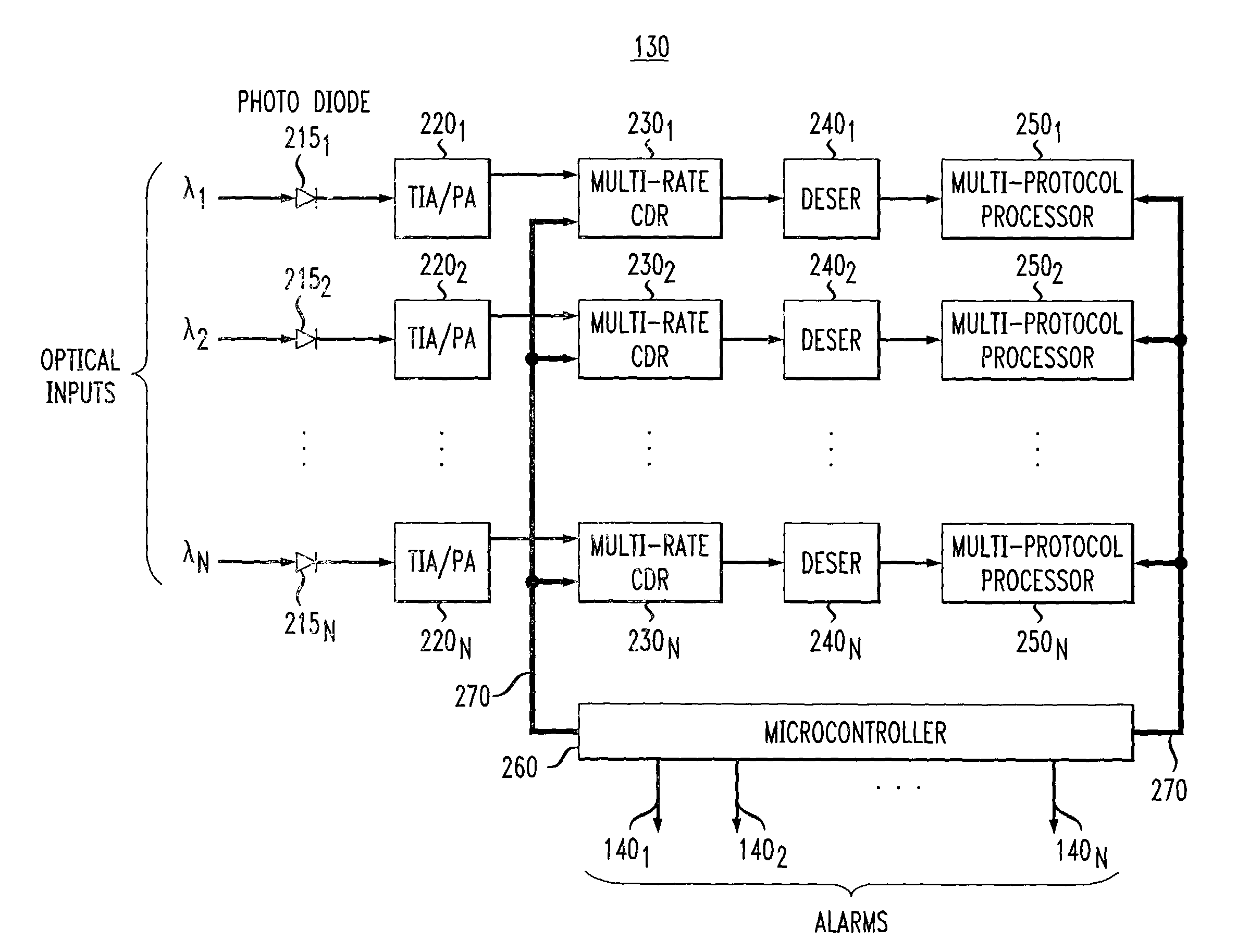
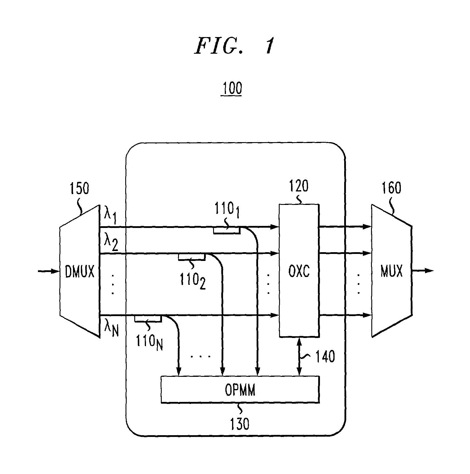
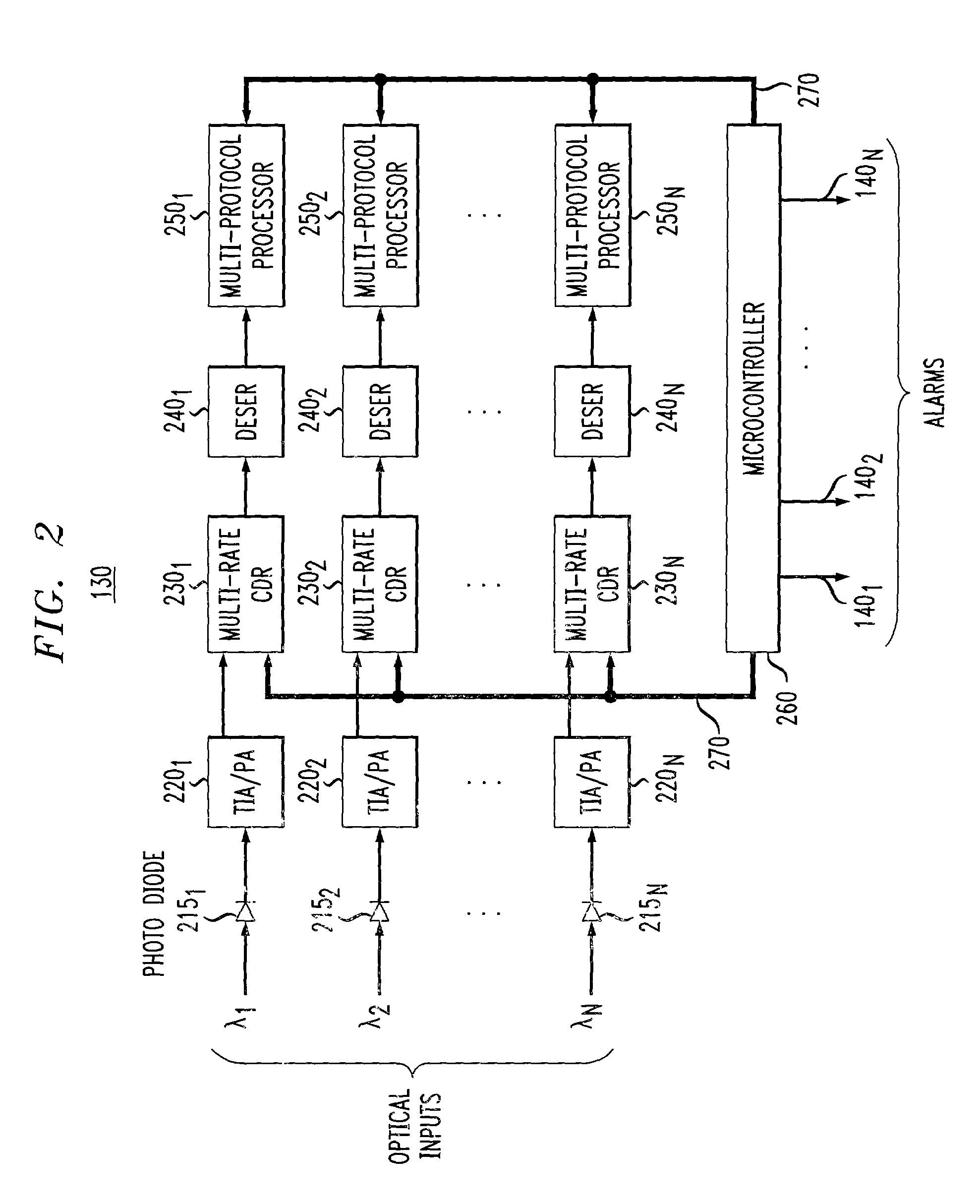
[0014]FIG. 1 depicts a high-level block diagram of a typical central office network node 100. The central office network node 100 of FIG. 1 includes a demultiplexer 150, a plurality of optical signal taps 1101–110N (collectively signal taps 110), an optical performance monitoring module (OPMM) 130, a communications bus 140, an optical cross connect (OXC) switch 120, and a demultiplexer 160. An optical signal is applied to the demultiplexer 150 and is thereby separated into a plurality of wavelengths λ1–λN (collectively optical signals λ). The optical signals λ are sampled using the optical taps 110, and the outputs of the optical taps 110 are applied to individual channels of the OPMM 130. The optical signals λ are subsequently applied as inputs to the OXC switch 120. Within the OPMM 130, the sampled optical signals λ are co...


PUM


Abstract

A method and apparatus for optical performance monitoring that provides for multi-rate and multi-protocol monitoring includes, identifying a protocol associated with each of a plurality of communication signals using respective data rates extracted therefrom, determining, for each of the plurality of communication signals, a respective bit-error rate (BER), and generating an alarm indicative of BER excursions beyond a protocol appropriate BER threshold level.

Description

FIELD OF THE INVENTION[0001]This invention relates to the field of optical communications and, more specifically, to signal monitoring.BACKGROUND OF THE INVENTION[0002]There is a growing trend toward all-optical re-configurable networks promising higher levels of data-rate and protocol transparency. However, in order to maintain these higher performance levels, signal quality monitoring must be provided at the optical layer. In such systems measurement of optical parameters is critical as it provides vital information regarding the performance of the system. Such information can then be used for diagnosis and repair of an optical network or for performance of optimization actions. One standard measurement of signal quality in optical systems has been the bit error rate (BER) of a system. The BER of a system is affected by two forms of signal degradation, noise and distortion. The measurement of such parameters must be accurate, have a wide range, and be performed in a timely manner ...

Claims


Application Information

Patent Timeline
IPC IPC(8): H04B10/08H04B10/02H04J14/02
CPCH04J14/02H04B10/07953
Inventor BELHADJ-YAHYA, CHEDLEYLEVY, DAVID S.
Owner LUCENT TECH INC
Why Eureka
Try Eureka