HVAC start-up control system and method

a control system and hvac technology, applied in the field of control application of hack & r system, can solve the problems of inconsistent climate control inside the building, waste of energy, and inability to adapt to changes, and achieve the effect of saving energy

Inactive Publication Date: 2006-08-29
YORK INT CORP
View PDF23 Cites 69 Cited by
  • Summary
  • Abstract
  • Description
  • Claims
  • Application Information

AI Technical Summary

Benefits of technology

[0007]One advantage of the present invention is that it is adaptive to day-to-day fluctuations in outside ambient temperature.
[0008]Another advantage of the present invention is that it requires a minimum number of data values saved to memory.
[0009]A further advantage of the present invention is that it saves energy by initiating operation of a HVAC&R system to achieve a setpoint temperature at a daily predetermined setpoint time.

Problems solved by technology

However, initiating the HVAC&R system too far in advance of the start of the setpoint time causes the HVAC&R system to reach the setpoint temperature before the setpoint time, thus wasting energy.
Conversely, initiating the HVAC&R system too close to the setpoint time causes the HVAC&R system to achieve the setpoint temperature after the setpoint time has passed, subjecting the occupants in the structure to temperature settings that are outside their comfort level until the setpoint temperature is achieved.
However, the controller of U.S. Pat. No. 4,522,336 is not adaptive, i.e., it does not take into account variations in the building, control system, or day-to-day differences in outside ambient temperature, and requires application of an arbitrary adjustment factor if the adjustment time falls outside a threshold range.
One drawback of this technique is that the arbitrary adjustment factor, as disclosed, can act to increase the time differential between the time the setpoint temperature should be reached and the time the setpoint temperature is actually reached, providing inconsistent climate control inside the building.

Method used


Image

  • HVAC start-up control system and method
  • HVAC start-up control system and method
  • HVAC start-up control system and method

Examples


Embodiment Construction

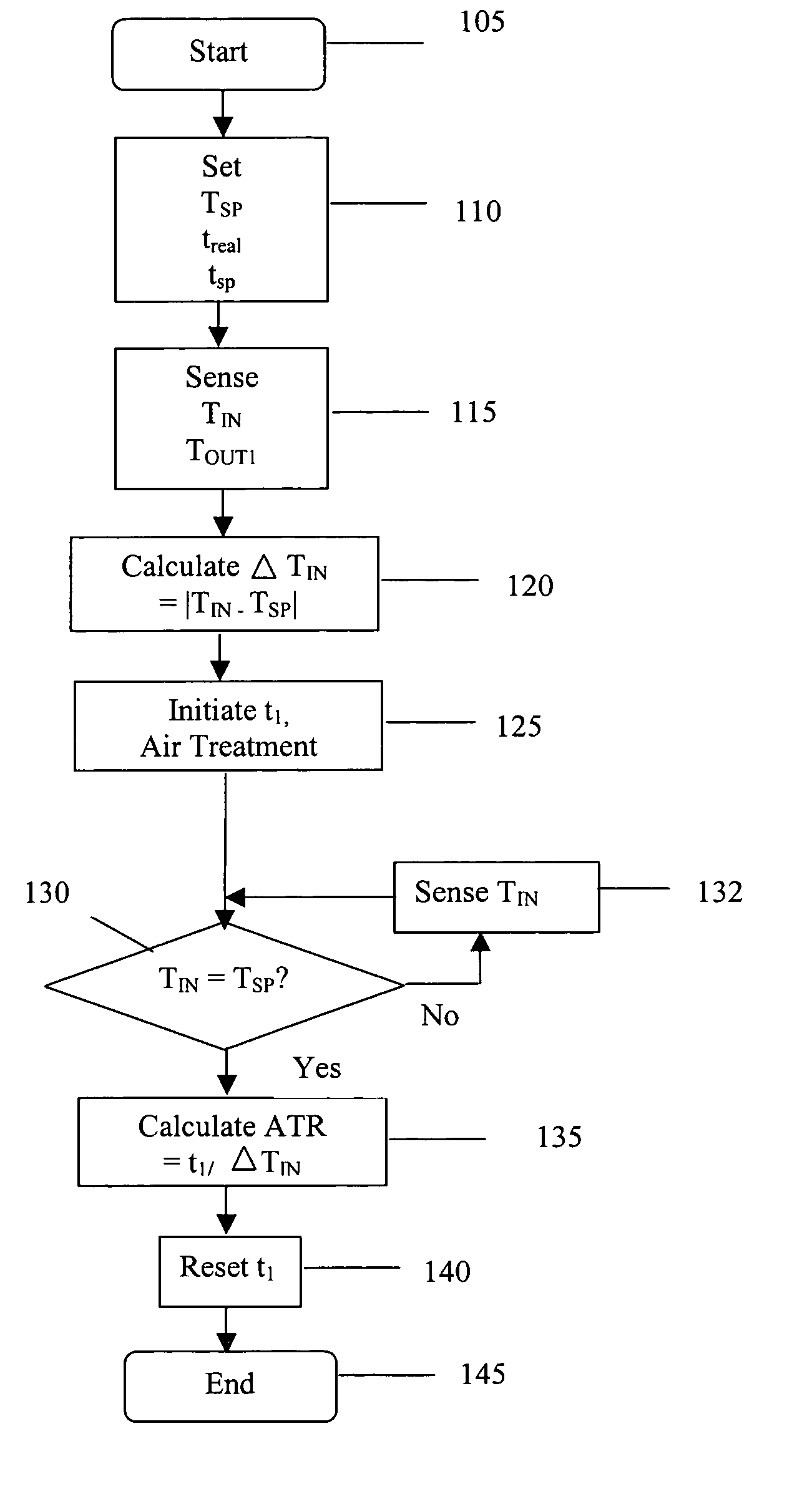
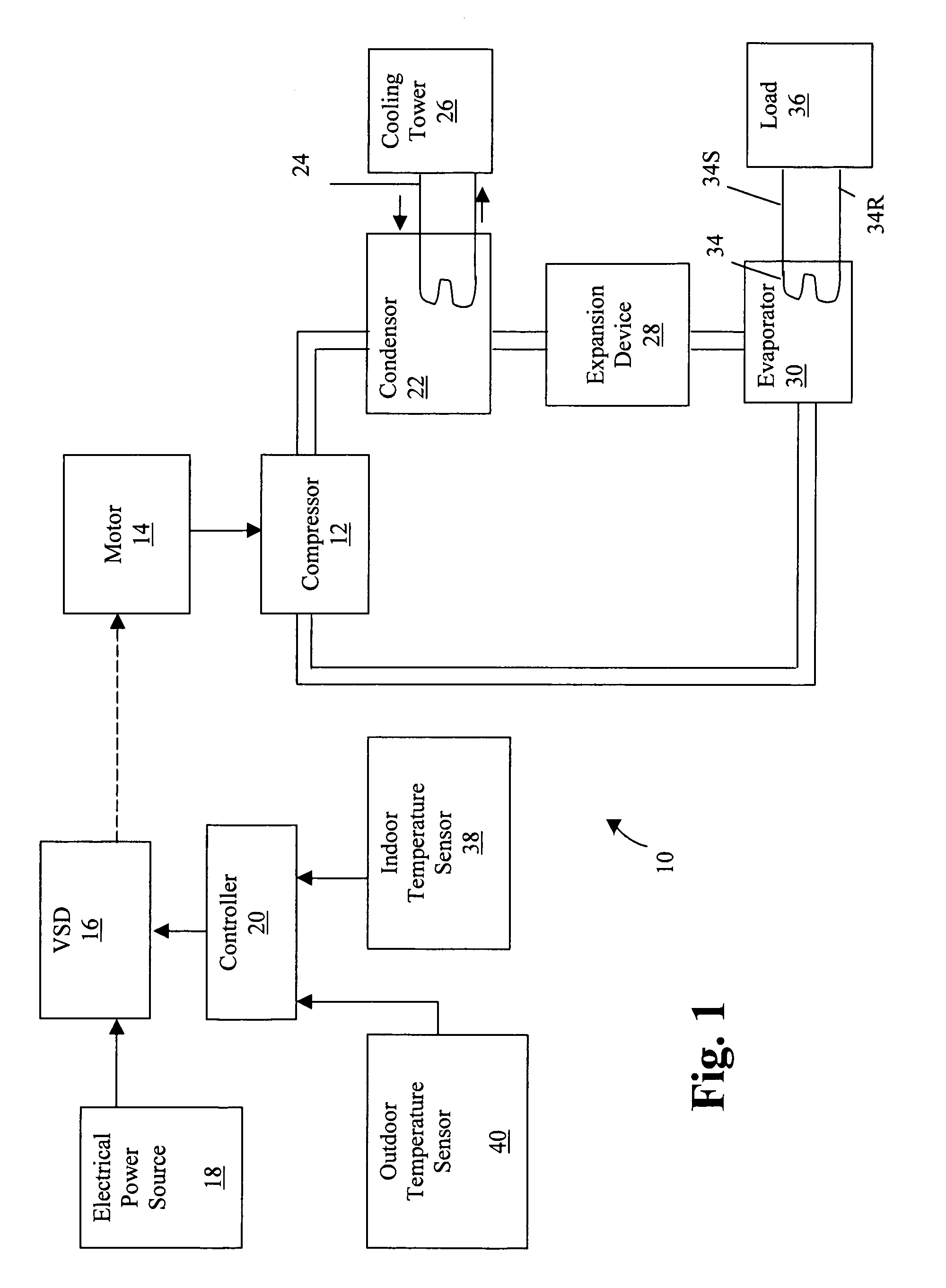
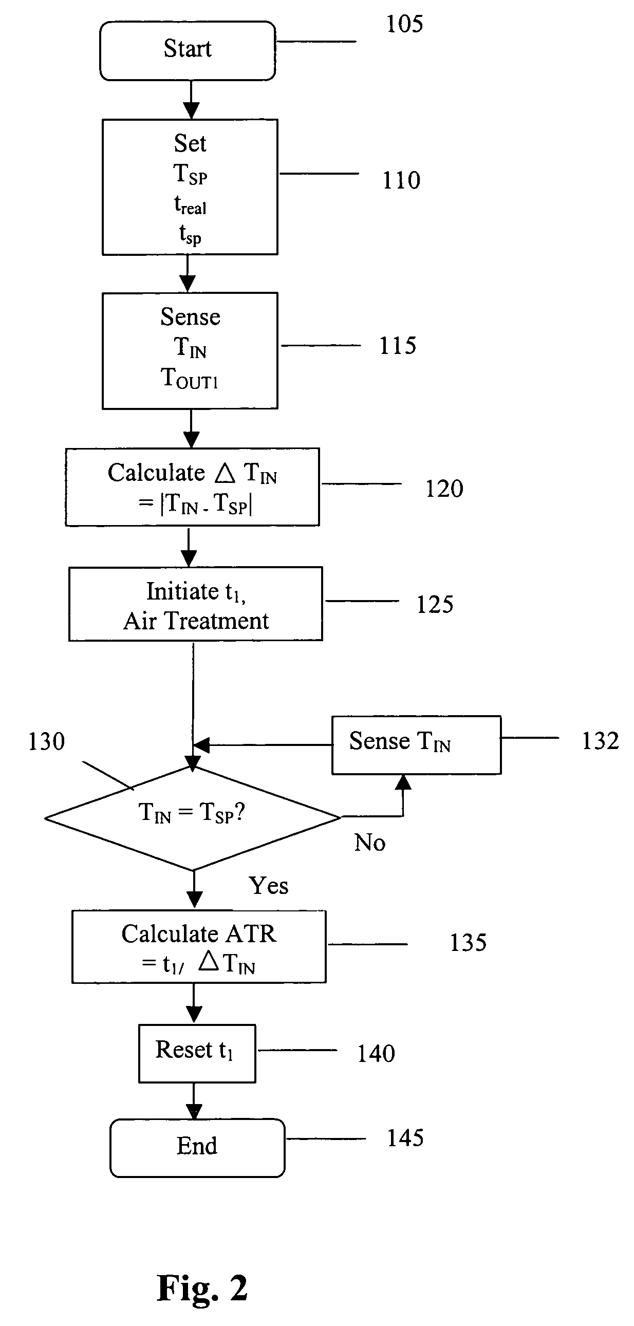
[0014]One embodiment of the heating, ventilation and air conditioning or refrigeration (HVAC&R) system 10 of the present invention is depicted in FIG. 1. Compressor 12 is connected to a motor 14 and inverter or variable speed drive (VSD) 16, for selectively controlling operational parameters, such as rotational speed, of the compressor 12. Compressor 12 is typically a positive displacement compressor, such as screw, reciprocating or scroll, having a wide range of cooling capacity, although any type of compressor may also be used. The controller 20 includes logic devices, such as a microprocessor or other electronic means, for controlling the operating parameters of compressor 12 by controlling VSD 16 and motor 14. AC electrical power received from an electrical power source 18 is rectified from AC to DC, and then inverted from DC back to variable frequency AC by VSD 16 for driving compressor motor 14. The compressor motor 14 is typically AC induction, but might also be Brushless Per...


PUM


Abstract

A controller controls operation of a HVAC&R device, bringing the temperature inside a structure from a first temperature to a second temperature at a predetermined time each day. Sensors sense the temperature both inside and outside the structure. A recovery time is calculated based upon a previously calculated air treatment rate of temperature recovery for the HVAC&R device to drive the temperature of the structure through a temperature change, the recovery time calculation being obtained by multiplying the difference between the sensed temperature inside the structure and the second temperature by the previously calculated air treatment rate. A correction factor is calculated based upon a relationship between the sensed outside temperature and a previously sensed outside temperature, the correction factor being added to obtain a corrected recovery time. The HVAC&R device is initiated at a time defined by the predetermined time subtracted from the corrected recovery time.

Description

BACKGROUND OF THE INVENTION[0001]The present invention relates generally to a control application for a HACK&R system. More specifically, the present invention relates to a system and method for start-up control of a HVAC&R system.[0002]To minimize energy costs, a structure having a heating, ventilation, air conditioning and refrigeration (HVAC&R) or air treatment system for achieving climate control uses temperature settings that are initiated at HVAC times. For example, in warmer weather, the temperature setting for the structure is set at a higher level during unoccupied hours, and set at a lower level during occupied hours. This lower level temperature setting is an occupied set point or occupied setpoint temperature. It is desirable for the HVAC&R or air treatment system to achieve the occupied setpoint temperature at the start of the time period or setpoint time corresponding to the occupied hours, typically the start of a work shift. To accomplish this, the HVAC&R system must...

Claims


Application Information

Patent Timeline
Patent Type & Authority Patents(United States)
IPC IPC(8): G05D23/00F23N5/20F24F11/00F25B49/02G05B13/00
CPCF24F11/006F24F2011/0013F24F11/30F24F2110/12F24F11/62F24F11/52
Inventor RAYBURN, RONALD RICHARD
Owner YORK INT CORP
Why Eureka
Try Eureka