Method and apparatus for diagnosing difficult to diagnose faults in a complex system

a complex system and fault technology, applied in the field of machine diagnostics, can solve problems such as difficult for field engineers to accurately review and comprehend information and successfully diagnose faults, complex machines may generate error logs, and limited scope of rules or knowledge stored in the repository

Inactive Publication Date: 2006-08-29
GENERAL ELECTRIC CO
View PDF56 Cites 81 Cited by
  • Summary
  • Abstract
  • Description
  • Claims
  • Application Information

AI Technical Summary

Benefits of technology

[0017]Once the formerly no trouble found events have been analyzed and the underlying cause detected, this information can be loaded into an expert system, case-based reasoning tool, or other diagnostic processing tool. Now, when fault log information and operational parameters are received from a machine, the diagnostic tool is more likely to identify a specific cause, thus avoiding the declaration of a no trouble found situation, which was so prevalent in the prior art.

Problems solved by technology

Because the malfunction can impair the ability of the owner to conduct business efficiently and cost effectively, it is essential to accurately diagnose and quickly repair the machine.
Such complex machines may generate an error log, containing information describing the sequence of events that occurred during both routine operation and during any malfunction situation.
However, if the error log is voluminous (the usual case for large complex devices) and certain entries have an uncertain relationship or perhaps no relationship to a specific malfunction, it will be very difficult for the field engineer to accurately review and comprehend the information and successfully diagnose the fault.
One disadvantage associated with such conventional diagnostic expert systems is the limited scope of the rules or knowledge stored in the repository.
The process of knowledge extraction from experts is time consuming, error prone and expensive.
Finally, the rules are brittle and cannot be updated easily.
A problem with using an artificial neural network for diagnosing machine malfunctions is that the neural network does not produce explicit fault correlations that can be verified by experts and adjusted if desired.
In addition, the conventional steps of training an artificial neural network do not provide a measure of its effectiveness so that more data can be added if necessary.
Also, the effectiveness of the neural network is limited and does not work well for a large number of variables.
Unfortunately, for a continuous fault code stream, any or all possible faults may occur from zero times to an infinite number of times, and the faults may occur in any order, so the structure of the fault log data is not amenable to easy diagnosis.
This feature of comparing error logs based on the sequence in which certain events occur represents a limitation on the process for determining the malfunction using historical error log data.
Generally this is occasioned by the intermittent nature of the fault or because the complexity of the system obscures the fault condition to a repair technician whose skills may be deficient in some area relevant to the system.
In some situations, repair personnel may be unable to recreate the fault at the maintenance center.
Later, the system may experience a repeat failure due to the same problem, requiring another attempt at diagnosis and repair.
Further, and disadvantageously, the inability to identify the root cause of the locomotive problem may result in the problem status remaining in an open condition for an extended period of time.
This is detrimental to efficient operation of the railroad, as the operator would like to identify, diagnose and close faults as early and as efficiently as possible.
A further complication to the diagnosis and repair problem may be due to the site where the diagnosis and repair is first attempted.
As a result, certain locomotive faults are incapable of being detected and thoroughly analyzed, dependent upon the site where the analysis takes place, again leading to a proliferation of “no trouble found” situations.

Method used


Image

  • Method and apparatus for diagnosing difficult to diagnose faults in a complex system
  • Method and apparatus for diagnosing difficult to diagnose faults in a complex system
  • Method and apparatus for diagnosing difficult to diagnose faults in a complex system

Examples


Embodiment Construction

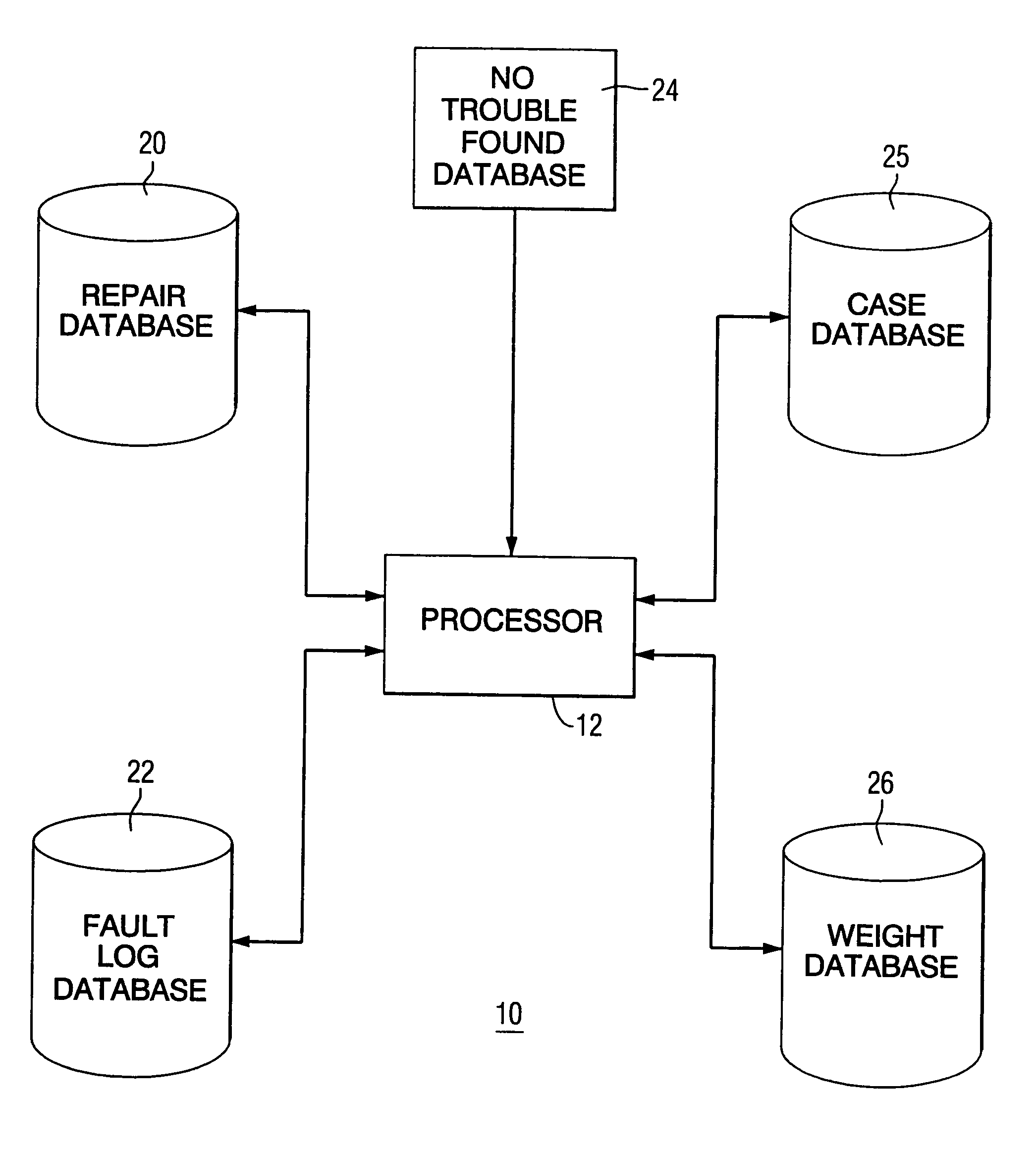
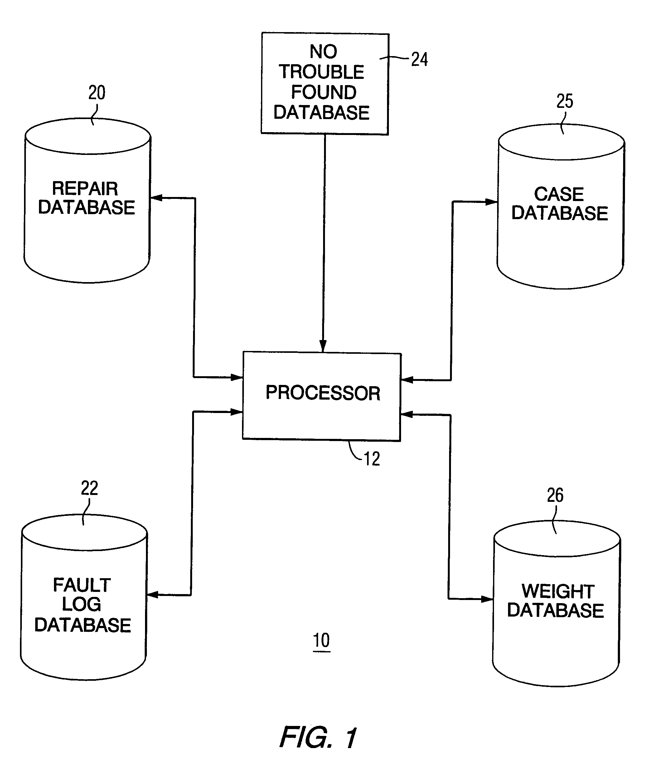
[0027]FIG. 1 diagrammatically illustrates one embodiment of the diagnostic system 10 of the present invention for analyzing no trouble found events to identify fault patterns and correlations of these patterns with certain faults. The diagnostic system 10 provides a process for automatically harvesting or mining repair data describing related and unrelated repairs and fault log data from one or more machines, such as locomotives. The diagnostic system 10 generates weighted repair and distinct fault cluster combinations that are diagnostically significant predictors of the repair action that will resolve a newly identified fault in a malfunctioning machine, including a no trouble found event. Thus, the historical data facilitate later analysis of new fault log data from a malfunctioning locomotive. In one embodiment of the invention, the diagnostic system 10 can jointly analyze the fault log and data operational parameters from the malfunctioning locomotive.

[0028]Although the present...


PUM


Abstract

A method and apparatus for determining the root cause of no trouble found events in a machine is disclosed. The actual faults occurring during a predetermined time interval prior to the no trouble found event are analyzed and correlated with the no trouble found events in an effort to identify those actual faults that have a high correlation with each no trouble found event. If a high correlation is not found, then the no trouble found event is analyzed off-line to determine the root cause.

Description

[0001]This application is a continuation of the application filed on Jul. 3, 2000, and assigned application Ser. No. 09 / 609,469, now U.S. Pat. No. 6,615,367, which claims the benefit of U.S. Provisional Application 60 / 162,045 filed on Oct. 28, 1999.BACKGROUND OF THE INVENTION[0002]The present invention relates generally to machine diagnostics, and more specifically to a system and method that improves diagnostic accuracy for failure conditions that are not possible to adequately diagnose and are therefore referred to as “no trouble found” conditions.[0003]A machine, such as a locomotive or other complex system used in industrial processes, medical imaging, telecommunications, aerospace applications, and power generation may include controls and sensors for monitoring the various systems and subsystems of the machine and generating a fault indication when an anomalous operating condition occurs. Because the malfunction can impair the ability of the owner to conduct business efficient...

Claims


Application Information

Patent Timeline
Patent Type & Authority Patents(United States)
IPC IPC(8): G06F11/00G05B23/02
CPCG05B23/0229
Inventor UNKLE, C. RICHARDRODDY, NICHOLAS EDWARD
Owner GENERAL ELECTRIC CO
Why Eureka
Try Eureka