Method and a control system for monitoring the condition of an industrial robot

a technology for industrial robots and control systems, applied in process control, process control, instruments, etc., can solve the problems of huge costs, insufficient experience of robot service technicians, and inability to detect or determine if an industrial robot is not performing according to its nominal performance, etc., to overcome the drawbacks and achieve the effect of simple method

Active Publication Date: 2010-11-02
ABB (SCHWEIZ) AG +1
View PDF5 Cites 87 Cited by
  • Summary
  • Abstract
  • Description
  • Claims
  • Application Information

AI Technical Summary

Benefits of technology

[0036]An advantage of the invention is that it is possible to overcome the drawbacks with respect to personnel judging the performance of the robot, as the invention provides a simple method for automatically monitor the current performance or condition of the robot.
is that it is possible to overcome the drawbacks with respect to personnel judging the performance of the robot, as the invention provides a simple method for automatically monitor the current performance or condition of the robot.

Problems solved by technology

However it is difficult to detect or determine if an industrial robot is not performing according to its nominal performance.
To find the cause of a failure the operator may have to try different hypothesis and it is therefore time consuming and often results in long stand-still periods for the robot causing huge costs.
Also due to frequent personal rotation today, operators of robot service technician staff do not have sufficient experience to diagnose and isolate a failure in the performance of the robot.
Further, if a failure in performance causing an emergency stop occurs, it is difficult to isolate the problem cause and what link or part of the robot that needs special attention.

Method used


Image

  • Method and a control system for monitoring the condition of an industrial robot
  • Method and a control system for monitoring the condition of an industrial robot
  • Method and a control system for monitoring the condition of an industrial robot

Examples


Embodiment Construction

[0047]A number of embodiments of the present invention supported by the appended drawings are described below.

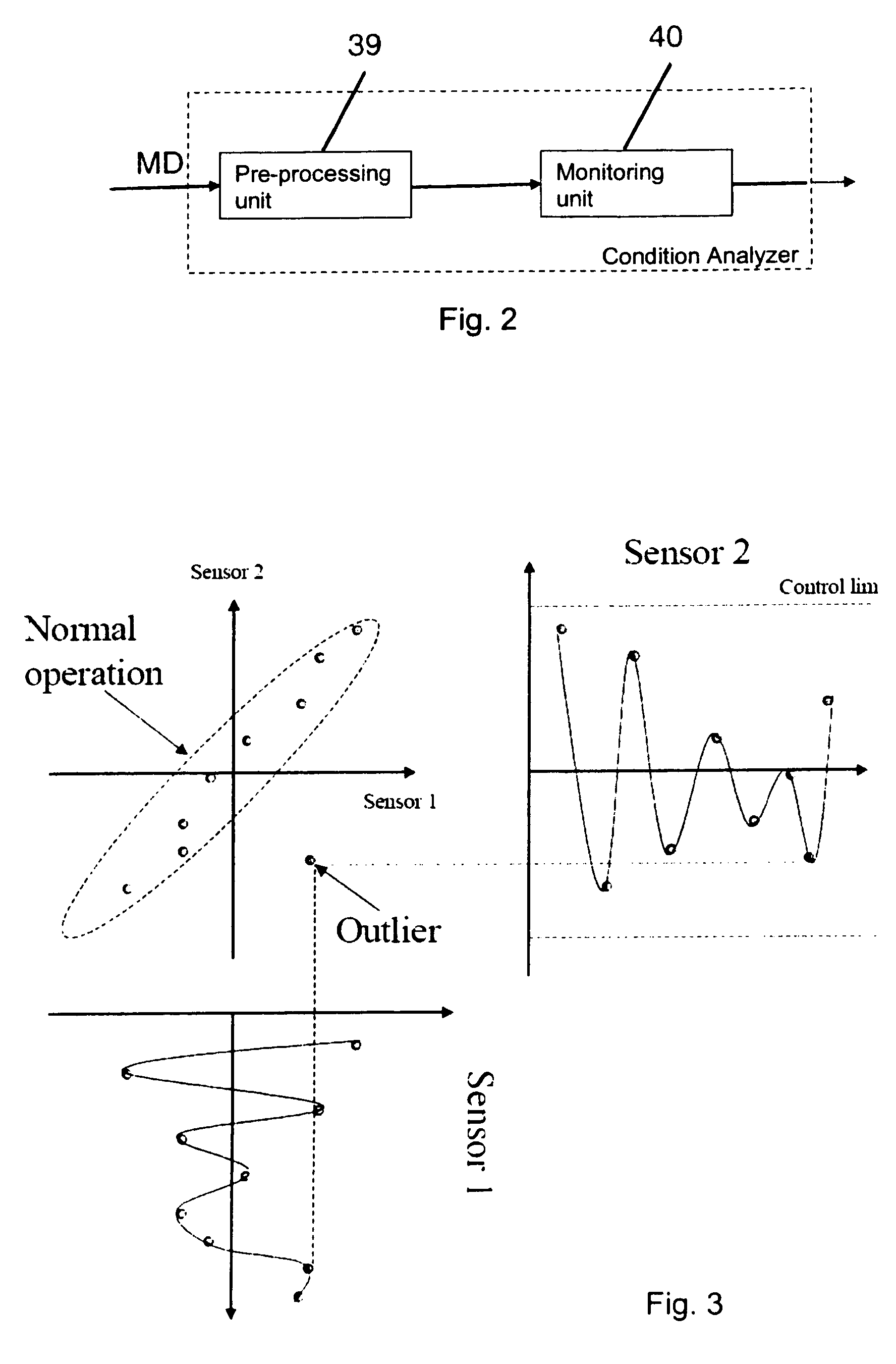
[0048]Primarily, an overview of an industrial robot system is presented to indicate examples of input signals assembled from different sensors distributed throughout the robot system, as well as calculators for providing the condition analyzer with selected signals.

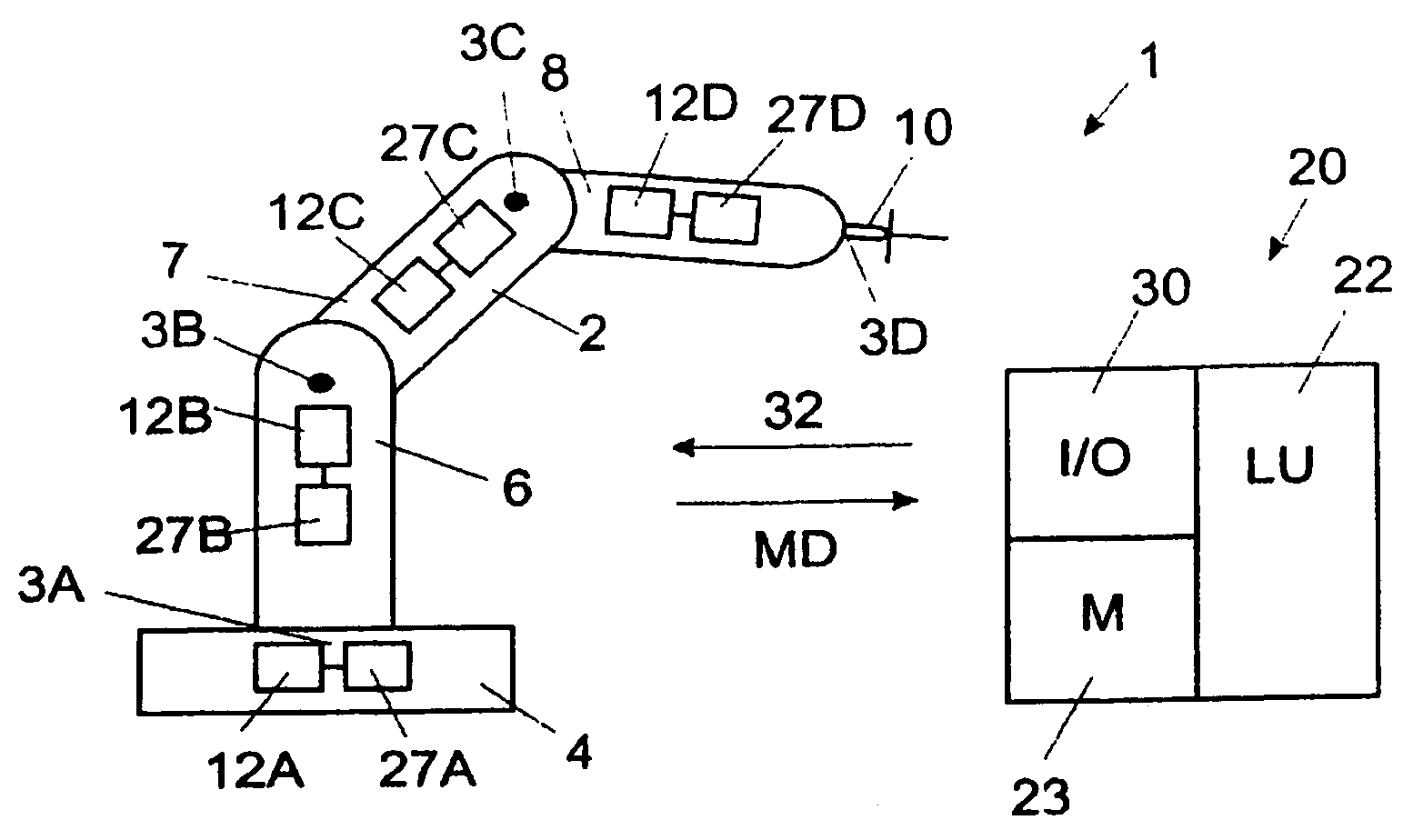
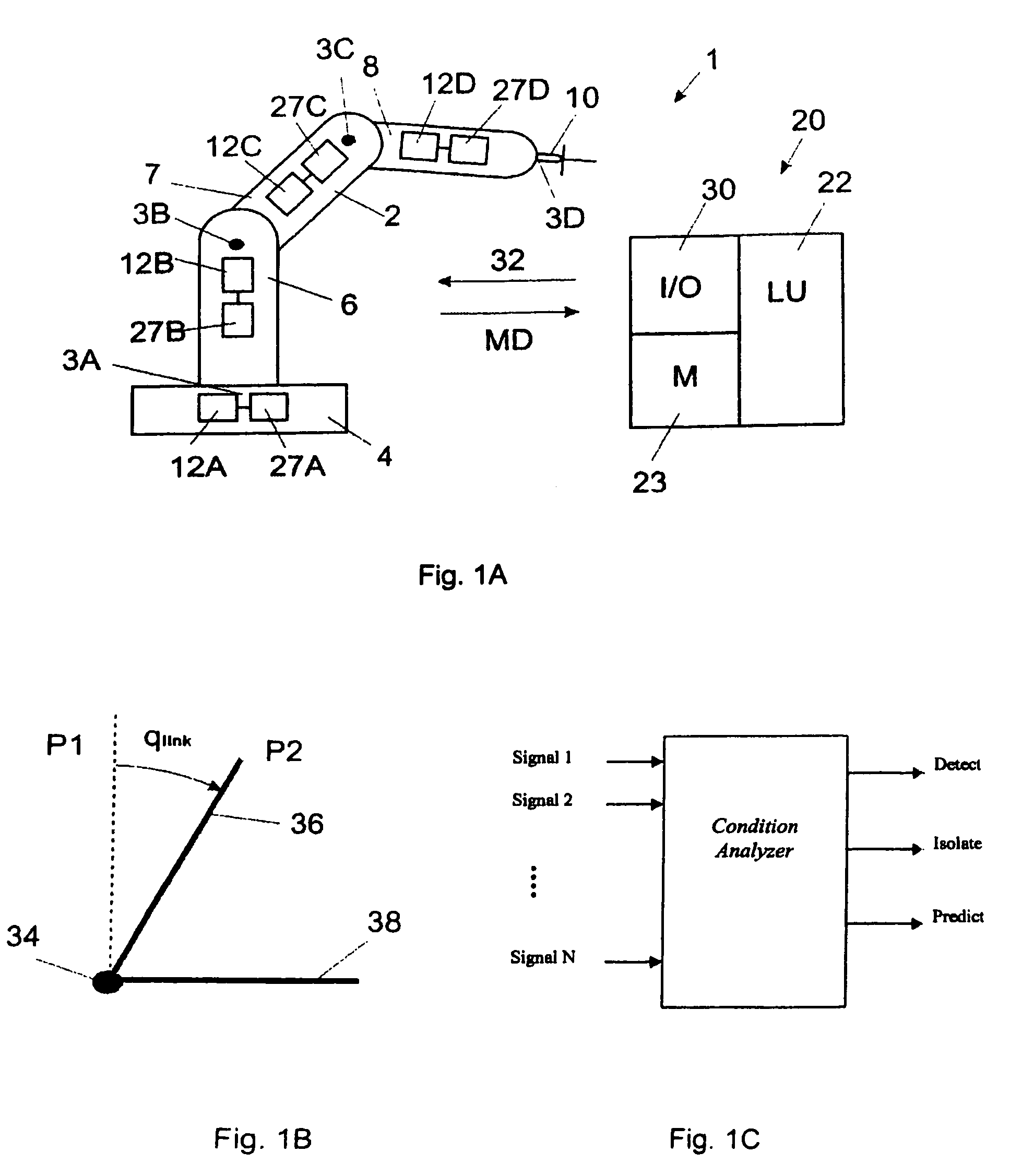
[0049]FIG. 1A shows an example of an industrial robot 1 comprising a manipulator 2 and a control system. The industrial robot has a plurality of links movable relative to each other about a plurality of joints 3A, 3B, 3C, 3D, in this case rotatable in relation to each other around an axis of rotation. The links are in this case robot parts, such as a stand 4, robot arms 6, 7, 8, and a wrist 10 comprising a turn disc. The industrial robot comprises a plurality of motors 12A, 12B, 12C and 12D controlling the position and speed of the links. The control system is illustrated as a simplified block diagram. The control...


PUM


Abstract

An industrial robot diagnostic method including performing a condition analysis utilizing at least two selected input signals, wherein each selected input signal indicates a condition related to a property of the industrial robot, performing an analysis of any combination of the selected input signals utilizing a signal modeling of the signals and outputting from the condition analyzer a result being at least one of: a detection of a malfunction of the robot system, an identification of a root cause failure in the robot system and prediction of a potential malfunction in the robot system. Also an industrial robot system utilizing the method.

Description

CROSS-REFERENCE TO RELATED APPLICATIONS[0001]This application claims priority to European patent application 07101800.6 filed 6 Feb. 2007.TECHNICAL FIELD[0002]The present invention is concerned with monitoring the condition of an industrial robot. The invention is particularly useful for detecting and predicting a malfunction of the robot.BACKGROUND ART[0003]An industrial robot comprises a manipulator and a control system. The manipulator comprises links movable relative to each other about a plurality of joints. The links are different robot parts such as a base, arms, and wrist. Each joint has joint components such as a motor, motor gear and motor bearings. The movements of the manipulator are driven by the motors. The control system comprises one or more computers and drive units for controlling the manipulator. The speeds and accelerations of the links are controlled by the control system of the robot that generates control signals to the motors.[0004]Industrial robots are used ...

Claims


Application Information

Patent Timeline
Patent Type & Authority Patents(United States)
IPC IPC(8): G01B3/00G01B3/44
CPCB25J9/1674G05B2219/33299G05B2219/34427G05B2219/34477G05B2219/37325G05B2219/37511G05B2219/39413
Inventor SJOSTRAND, NICLASBLANC, DOMINIQUETAVALLAEY, SHIVA SANDER
Owner ABB (SCHWEIZ) AG
Why Eureka
Try Eureka