Method of forming filament-reinforced composite thermoplastic pressure vessel fitting assembly

a technology of composite thermoplastics and fitting assemblies, which is applied in the field of fitting assemblies for filament-reinforced composite thermoplastic pressure vessels, can solve the problems of affecting the manufacture of vessels, pressure vessels cannot be added to the above conventional thermosets and thermoplastics, and the mechanical strength of pressure vessels is substantially weakened, so as to facilitate the resizing and/or relocation of ports, the effect of facilitating the manufacture of vessels

Active Publication Date: 2006-09-05
ENPRESS
View PDF3 Cites 11 Cited by
  • Summary
  • Abstract
  • Description
  • Claims
  • Application Information

AI Technical Summary

Benefits of technology

[0014]Filament-reinforced pressure vessels formed in accordance with the invention provide several advantages over the prior art. The method readily facilitates the resizing and / or relocation of ports without the need for new molds, excessive preparation or labor, or expensive equipment. Vessels having ports formed in accordance with the invention retain their mechanical strength. Further, the openings for the fitting assembly can be formed in the vessel wall following application of the reinforcing layer, greatly facilitating manufacture of the vessel.

Problems solved by technology

Unfortunately, a port cannot usually be added to the aforementioned conventional thermoset and thermoplastic pressure vessel simply by drilling or cutting a hole in the vessel wall and bonding a port structure around the hole (or vice versa).
It is commonly believed that, unless the port structure is bonded to the thermoplastic liner and the thermoset and filament reinforced outer layer, the mechanical strength of the pressure vessel is substantially weakened.
Moreover, in conventional vessels, severing the continuous filament reinforcement undermines the strength of the vessel.

Method used


Image

  • Method of forming filament-reinforced composite thermoplastic pressure vessel fitting assembly
  • Method of forming filament-reinforced composite thermoplastic pressure vessel fitting assembly
  • Method of forming filament-reinforced composite thermoplastic pressure vessel fitting assembly

Examples


Embodiment Construction

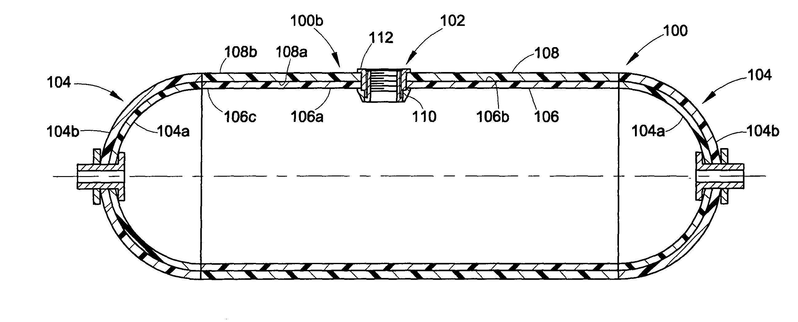
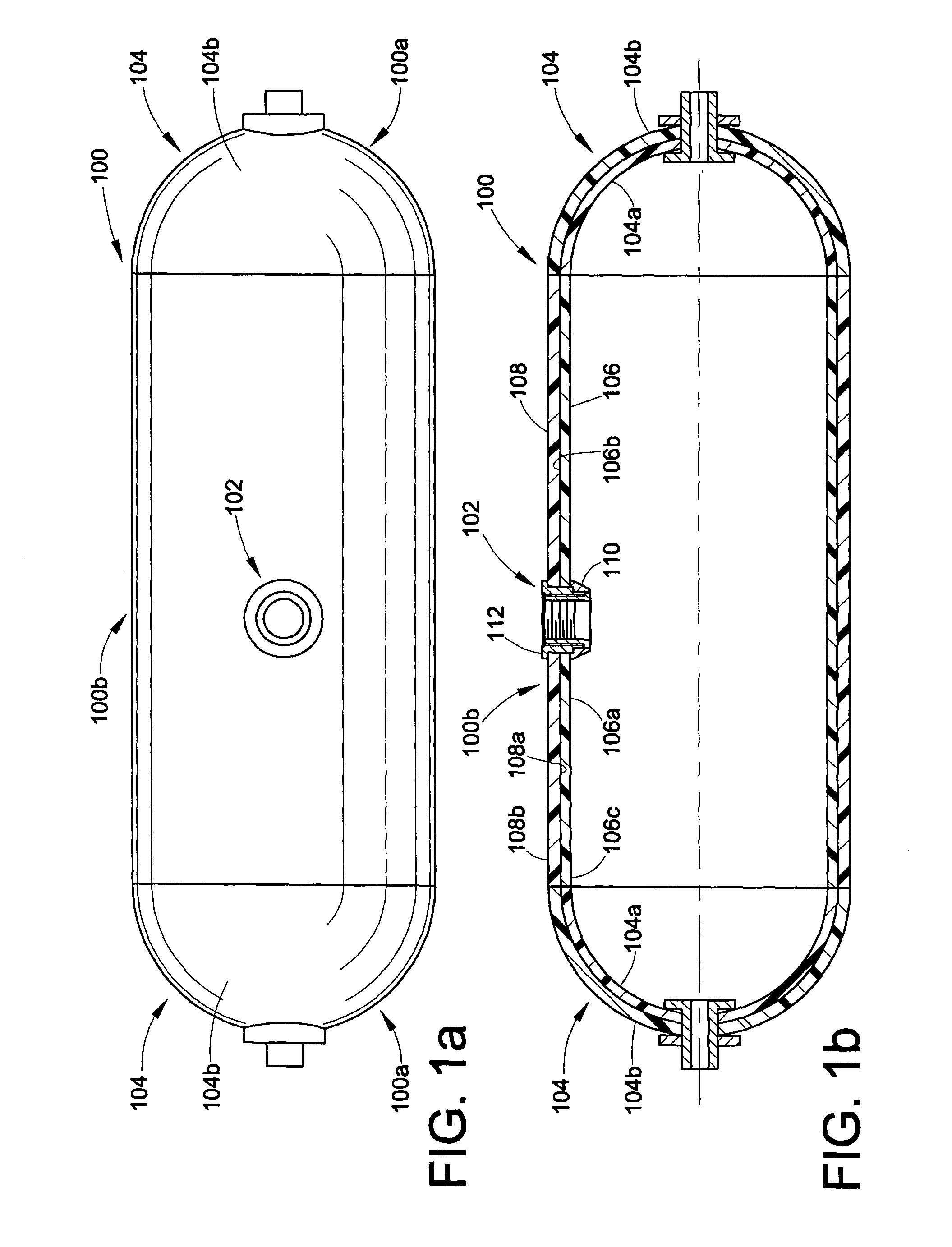
[0021]An exemplary filament-reinforced thermoplastic pressure vessel 100 according to the invention is shown in FIG. 1a. The vessel 100 defines a fluid-containment cavity and has at least one fitting assembly 102 formed in the vessel sidewall 100b. In the embodiment shown in FIG. 1a, the fitting assembly 102 is formed in the vessel sidewall 100b. However, it is considered apparent that plural fitting assemblies 102 in accordance with the present invention may readily be installed in a single vessel 100.

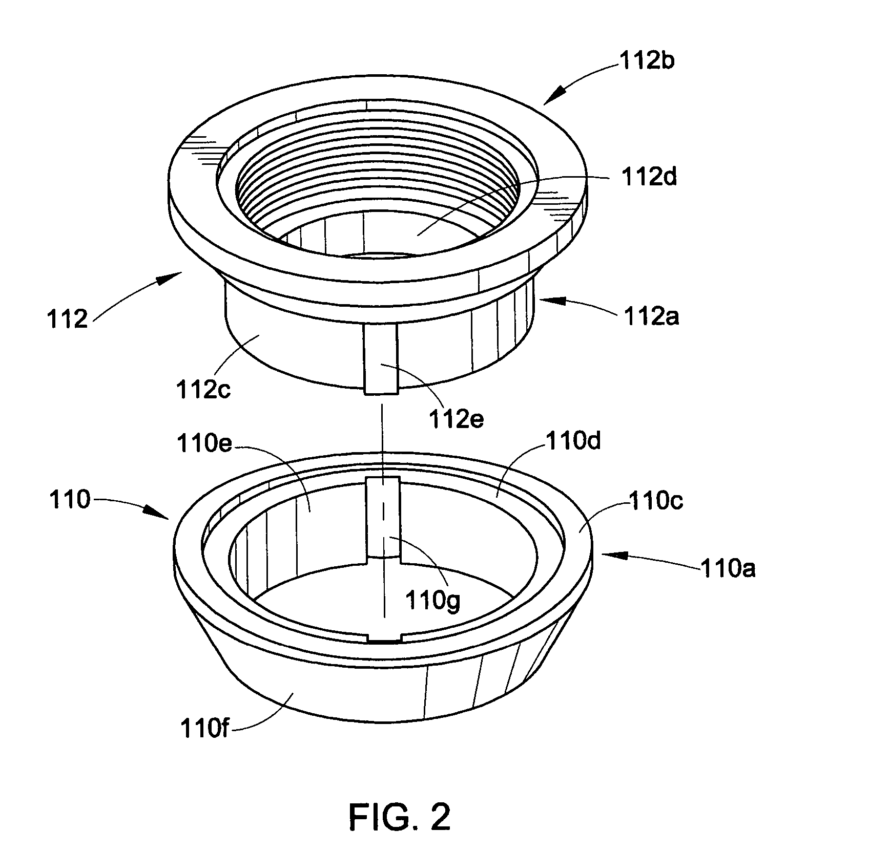
[0022]FIG. 1b is a cross-sectional view through the vessel 100 and the fitting assembly 102. The vessel 100 includes a pair of domes or endcaps 104, an inner thermoplastic liner 106, and an outer reinforcing layer 108. The thermoplastic liner 106 is generally cylindrical, having an inner surface 106a, an outer surface 106b, and first and second ends 106c that are each bonded to one of the domes 104, respectively. The outer reinforcing layer 108 is formed from commingled thermoplastic ...


PUM

PropertyMeasurementUnit
mechanical strengthaaaaaaaaaa
corrosion resistanceaaaaaaaaaa
external forceaaaaaaaaaa

Abstract

A method of forming a fitting assembly in a filament-reinforced pressure vessel, and a pressure vessel having a fitting assembly secured therein. In the method, a first fitting portion is bonded to an inner surface of a thermoplastic liner in a fluid tight manner. A layer of commingled reinforcing filaments and plastic material is applied to an outer surface of the thermoplastic liner to form a vessel wall. A portion of the vessel wall adjacent to the opening bounded by the fluid-tight seal between the first fitting portion and the inner surface of the thermoplastic liner is removed. Then, a second fitting portion is bonded to the first fitting portion so as to define a port for access into the interior of the vessel.

Description

BACKGROUND OF THE INVENTION[0001]1. Field of the Invention[0002]The present invention relates generally to a fitting assembly for composite pressure vessels and, more specifically, to a fitting assembly for filament-reinforced composite pressure vessels and methods of forming the same.[0003]2. Description of Related Art[0004]Reinforced pressure vessels are preferred for use in many fluid-containment applications because they are substantially lighter in weight than pressure vessels formed of traditional materials such as steel, and provide exceptional mechanical strength and corrosion resistance. The term “fluid” refers to any material or substance that changes shape or direction uniformly in response to an external force imposed on it and includes not only liquids, but also gases and finely divided solids.[0005]The vessel wall of a filament-reinforced plastic pressure vessel is substantially continuous, and is formed of a composite laminated structure. The inner portion or layer of...

Claims


Application Information

Patent Timeline
Patent Type & Authority Patents(United States)
IPC IPC(8): B23Q3/00B29C65/02B29C41/04B29C70/08B29C70/72B29C70/86F17C1/00F17C1/06F17C1/16
CPCB29C70/086B29C70/86F17C1/06F17C1/16F17C2209/221Y10T29/49895F17C2223/0123F17C2223/0153F17C2223/035F17C2223/036F17C2260/011F17C2260/012F17C2260/013B29C41/04B29C70/72B29L2031/7156B29L2031/7172F17C2201/0109F17C2201/035F17C2201/054F17C2201/056F17C2203/0604F17C2203/0619F17C2203/066F17C2203/0665F17C2203/067F17C2203/0673F17C2205/0305F17C2205/0397F17C2209/2109F17C2209/2118F17C2209/2127F17C2209/2145F17C2209/2154Y10T29/49801Y10T29/49826F17C2209/222
Inventor CARTER, THOMAS G.
Owner ENPRESS
Why Eureka
Try Eureka