Fixed pin bow sight

a fixed pin and sight technology, applied in the field of sight pin construction of bow sights, to achieve the effect of being vastly more accura

Inactive Publication Date: 2006-09-05
AFSHARI ABBAS BEN
View PDF22 Cites 15 Cited by
  • Summary
  • Abstract
  • Description
  • Claims
  • Application Information

AI Technical Summary

Benefits of technology

[0020]By providing a sight pin with multiple sight tips in a pre-configured arrangement, the sight tips can be relatively precisely (within manufacturing tolerances) placed along the sight pin at the appropriate locations. Such a configuration i

Problems solved by technology

Thus, in practicality, the sight may be fixed relative to the bow and not necessarily adjustable thereto in

Method used


Image

  • Fixed pin bow sight
  • Fixed pin bow sight
  • Fixed pin bow sight

Examples


Embodiment Construction

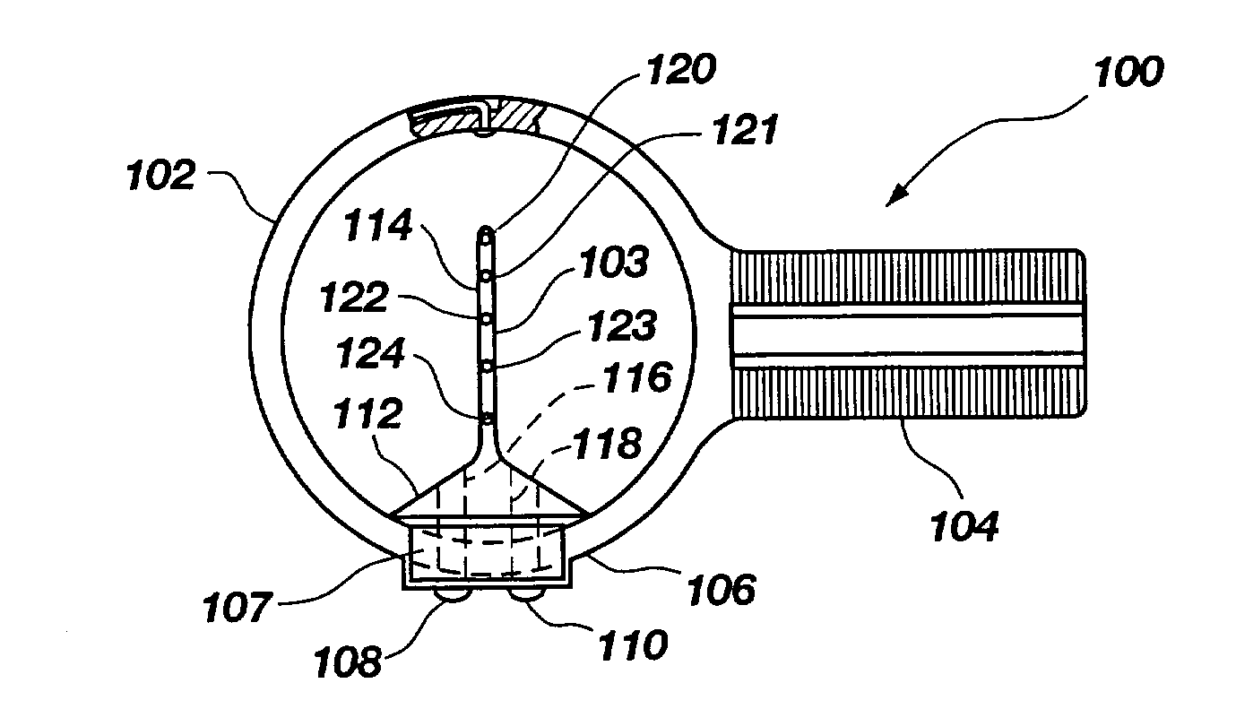
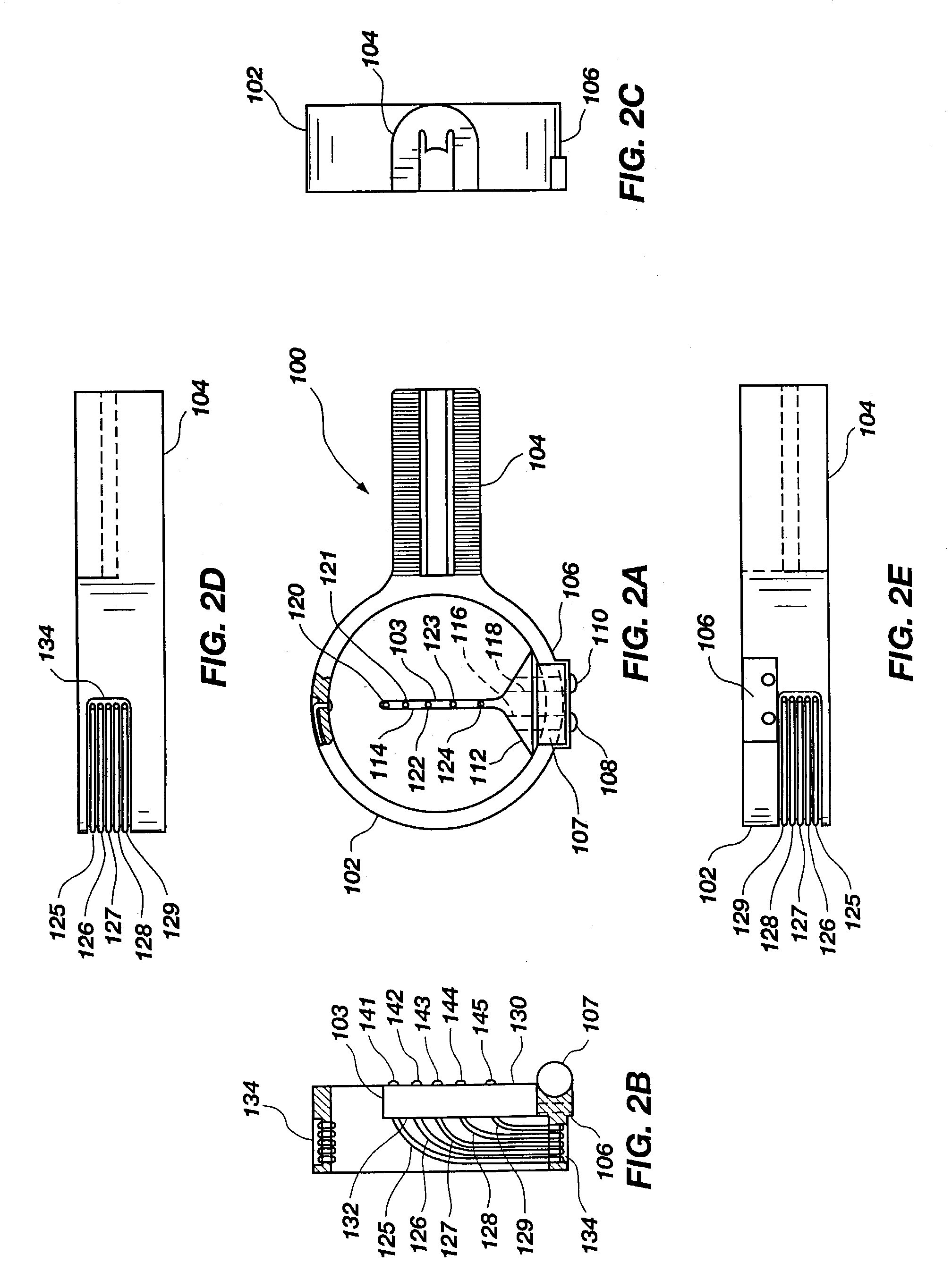
[0036]FIGS. 2A–2E illustrate a first embodiment of a bow sight, generally indicated at 100, in accordance with the principles of the present invention. The sight 100 is comprised of a pin guard portion 102 for protecting the sight pin 103 and a pin mounting portion 104 for mounting the sight 100 to a mounting bracket (not shown). In this embodiment, the sight pin 103 is a separate component from the rest of the sight 100 and is attached to a pin mounting portion 106 as with fasteners 108 and 110. A leveling mechanism 107, such as a leveling bubble, is attached to the sight 100 proximate the pin mounting portion 106. The leveling bubble 107 is provided to allow an archer to ensure that the sight 100 is properly horizontally oriented when aiming the sight at a target to provide more accurate targeting.

[0037]The sight pin 103 is comprised of a base portion 112 configured for mounting the sight pin 103 to the pin mounting portion 106 of the sight 100 and for providing structural stabili...


PUM


Abstract

A fixed pin bow sight is comprised of a bow sight having an attachment portion, a sight pin mounting portion and a sight pin having a plurality of sight tips on said sight pin. Each of the sight tips are predisposed on the sight pin and spaced to provide accurate targeting of an arrow shot from a bow having a particular shooting speed. The spacing between sight tips is defined by the desired targeting distances from the bow. For example, the uppermost sight tip may be configured for a target that is twenty yards away with subsequent sight tips provided for ten yard increments (e.g., 30, 40, 50 and 60 yards). The sight tips are configured to be vertically aligned relative to the ground when firing the bow so that as the distance from target is increased the appropriate sight tip moves from top to bottom of the sight pin.

Description

BACKGROUND OF THE INVENTION[0001]1. Field of the Invention[0002]This invention relates generally to sights for archery bows and, more specifically, to bow sights having sight pin constructions that are pre-set for a particular bow so as to reduce the amount of adjustment necessary to sight in the bow sight to the bow.[0003]2. Description of the Art[0004]Archery bow sights utilizing a plurality of sight pins have been known in the art for many years. Typically, these sights use a bracket or other mounting structure for mounting the sight to a bow. The sight is commonly comprised of a pin plate, a pin guard, and a plurality of sight pins which are secured to the pin plate and extend into a sight window formed by the pin guard. The sight is mounted to a bow in a manner so that when the bow string is drawn, the archer can look through a peep sight provided in the bow string and align the tip of a pin attached to the sight with a target. For sights utilizing a plurality of sight pins hav...

Claims


Application Information

Patent Timeline
IPC IPC(8): F41G1/467
CPCF41G1/467
Inventor AFSHARI, ABBAS BEN
Owner AFSHARI ABBAS BEN
Why Eureka
Try Eureka