Operating method for a rotary engine and a rotary internal combustion engine

a technology of internal combustion engine and rotary engine, which is applied in the direction of rotary or oscillating piston engine, rotary piston engine, engine lubrication, etc., can solve the problems of poor ecological compatibility, low compression stroke efficiency, fuel inefficiency

Inactive Publication Date: 2006-09-05
DOMIKO TRADING
View PDF16 Cites 4 Cited by
  • Summary
  • Abstract
  • Description
  • Claims
  • Application Information

AI Technical Summary

Benefits of technology

[0006]The problems solved by the present invention are improving fuel efficiency and ecological compatibility of an engine, providing it with the ability to set advance ignition, increasing the rotation frequency of a working shaft and decreasing its vibration, as well as making the manufacturing of such engine more cost effective.
[0008]Due to these features of the method of operation of a rotary engine and the rotary internal-combustion engine of the invention, in particular due to moving the compression chamber outside the working chamber and in relation to this chamber by the rotors, one may achieve more efficient application of active forces (due to the pressure from combustion materials within the combustible mixture) to a rotor mounted on an engine shaft.

Problems solved by technology

A disadvantage of such engine is that injection of compressed combustible mixture from the charging tank to the engine chamber lowers efficiency of the compression stroke.
Additionally, inability to set advance ignition at higher rotation results in fuel inefficiency and poor ecological compatibility.
This solution is disadvantageous in that unilateral dislocation of a rotor from an axis causes enhanced vibration in an engine due to sliding rotor blades.
Furthermore, inability to set advance ignition at higher rotation results in fuel inefficiency and lowering ecological compatibility.

Method used


Image

  • Operating method for a rotary engine and a rotary internal combustion engine
  • Operating method for a rotary engine and a rotary internal combustion engine
  • Operating method for a rotary engine and a rotary internal combustion engine

Examples


Embodiment Construction

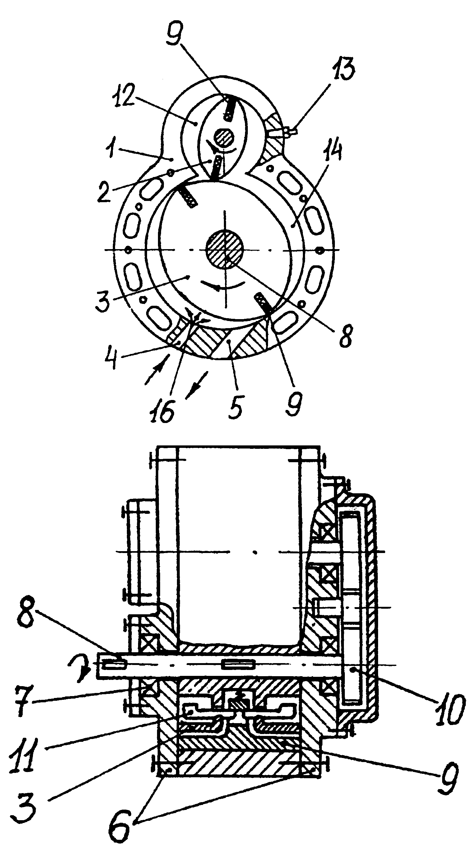
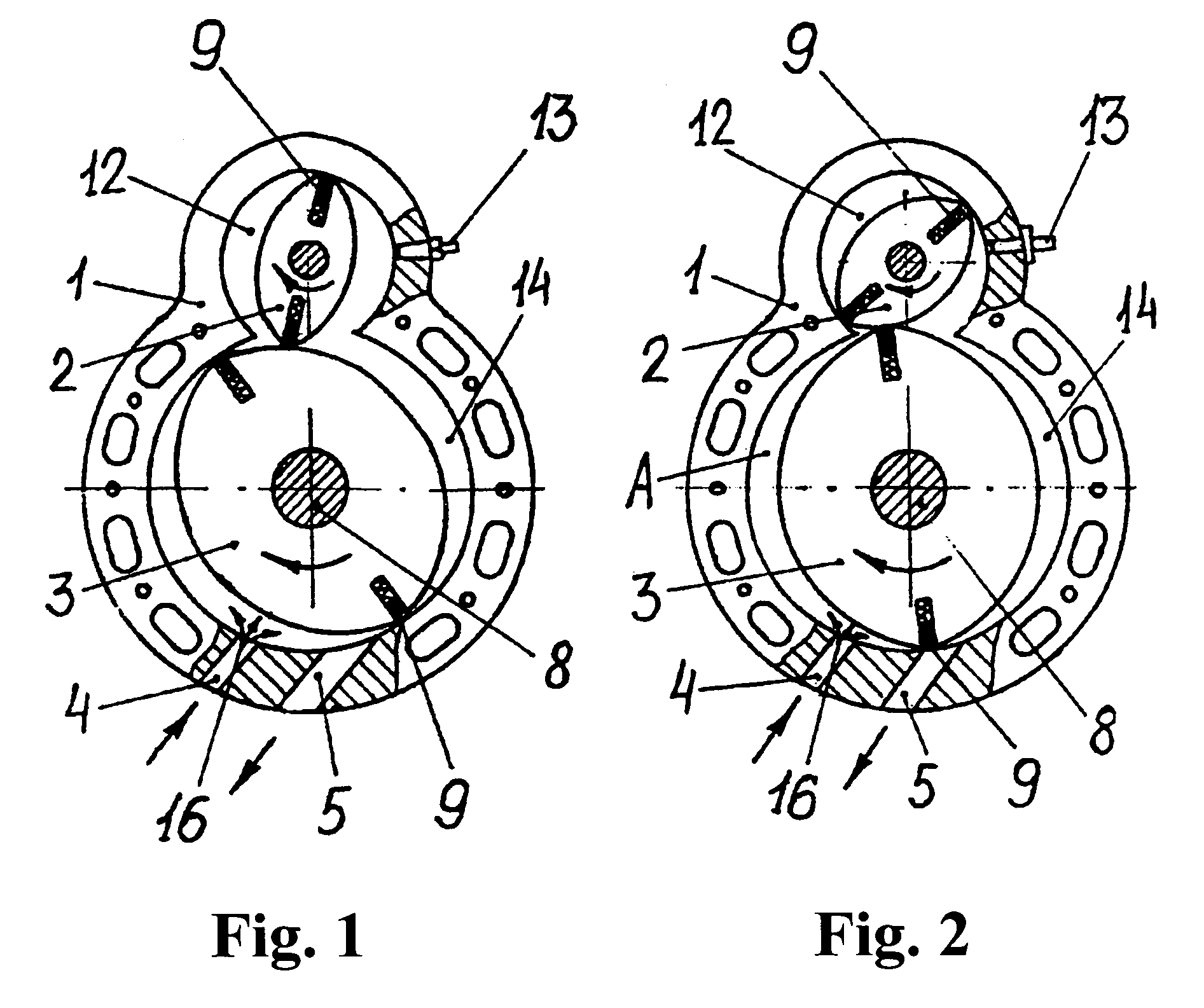
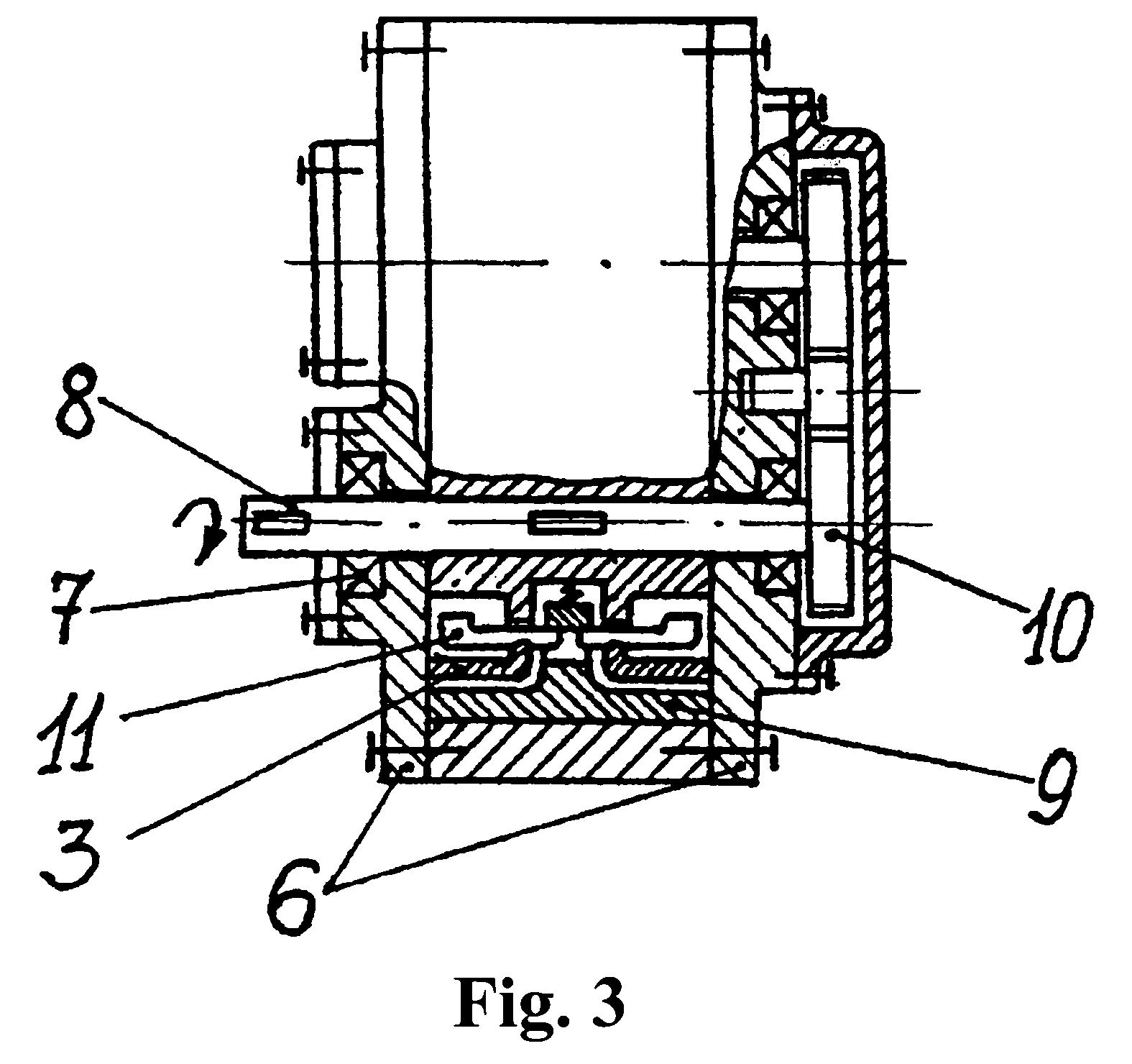
[0017]The rotary internal-combustion engine according to the invention comprises a housing 1 where rotors 2 and 3 are mounted in its chambers. The housing is provided with an intake port 4 and an exhaust port 5. The housing of the engine is also closed with lids 6 on which bearings 7 of the rotors are mounted co-axially with the chambers of the housing. The rotor 3 is connected with the working shaft 8 of the engine. The rotors comprise spring-loaded blades 9 and are connected with each other through the transmission 10 (for example, gear-type transmission) providing interrelated rotation of the rotors. The blades 9 may be equipped with the counter-loads 11 (FIG. 3) in order to reduce their pressing toward the housing of the engine by centrifugal forces during the operation of the engine. The compression chamber 12 holds a fuel injector or igniter plug 13. The screen may be made as a spring-loaded plate 15 (FIG. 7), as a gaseous (air) barrier 16 (FIGS. 1, 2, 4, 5, 6 in engines with ...


PUM


Abstract

The invention relates to propulsion engineering and particularly to internal-combustion engines. The problem solved by the present invention is improving fuel efficiency and ecological compatibility, as well as providing the ability to set advance ignition at higher rotation, increasing the rotation frequency of the working shaft and decreasing its vibration, thus making the manufacture of such engines more cost effective. This problem is solved by the operational rotor being oval-shaped when viewed in cross-section, whilst the compression rotor being square-shaped when viewed in cross-section.

Description

FIELD OF THE INVENTION[0001]The invention relates to propulsion engineering and particularly to methods of operation of rotary internal-combustion engines and their structures.PRIOR ART[0002]U.S. Pat. No. 3,951,111, F02B 53 / 08, 1976 discloses a method of operation of a rotary internal-combustion engine comprised of two rotors provided with two sliding blades forming together with flanges of slide valves a charging tank and an engine chamber, characterised in that its operation is based on a four-stroke cycle in which a compressed and ready for ignition combustible mixture is cross-injected between the charging tank of the first cylinder and the engine chamber of the second cylinder after a compression stroke.[0003]A disadvantage of such engine is that injection of compressed combustible mixture from the charging tank to the engine chamber lowers efficiency of the compression stroke. Additionally, inability to set advance ignition at higher rotation results in fuel inefficiency and p...

Claims


Application Information

Patent Timeline
Patent Type & Authority Patents(United States)
IPC IPC(8): F02B53/04F01C1/08F01C21/00F02B53/00F02B53/02F02B1/00F02B55/14
CPCF01C1/28F02B55/14Y02T10/17F02B53/00Y02T10/12F02B53/02
Inventor STANISHEVSKAYA, ELENA ANATOLYEVNA
Owner DOMIKO TRADING
Why Eureka
Try Eureka