Submersible lighting

a technology of driving lights and water-reflectors, which is applied in lighting and heating equipment, lighting apparatus, etc., can solve the problems of driving lights being submerged in water, difficult to remove, and not completely sealed space between the lens and the reflector of lights

Inactive Publication Date: 2006-09-05
HELLA AUSTRALIA
View PDF6 Cites 52 Cited by
  • Summary
  • Abstract
  • Description
  • Claims
  • Application Information

AI Technical Summary

Benefits of technology

[0004]According to one aspect of the present invention there is provided a submersible light comprising a lens sealed to the front of a reflector, a replaceable light source housed in an aperture in the reflector, a pressure member positioned behind the reflector to define an air chamber open at the base of the light but in sealed communication with the aperture whereby, in use, as the light becomes submerged liquid enters the base of the pressure member to pressurise the air within the pressure member to in turn form a pocket of pressurised air in the space between the lens and the reflector and thus prevent entry of liquid into that space.

Problems solved by technology

The fact that the bulbs are replaceable means that the space between the lens and reflector of the lights is not totally sealed.
Thus, in situations where an off road vehicle passes through deep water, driving lights can be submerged in water.
Once moisture enters the space between the reflector and the lens it is extremely difficult to remove.
The efficiency of the light is consequently substantially impaired.

Method used


Image

  • Submersible lighting
  • Submersible lighting

Examples


Embodiment Construction

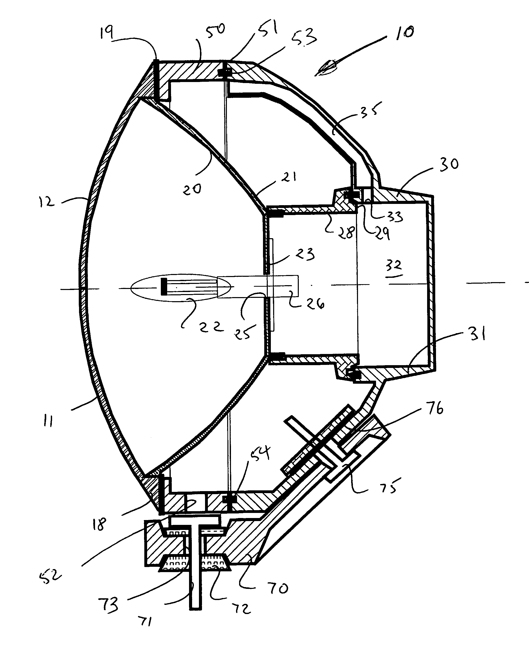
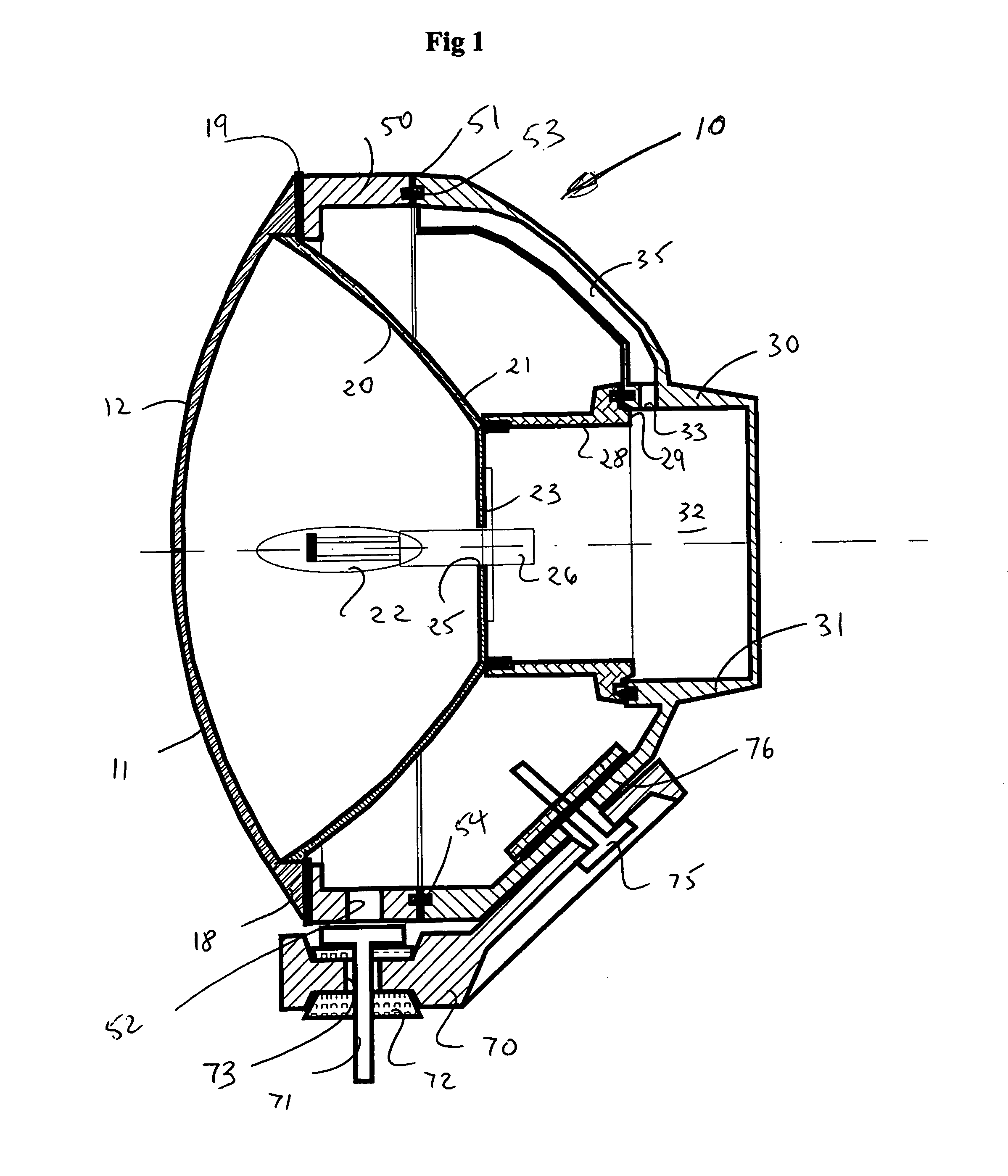
[0006]An embodiment of the present invention will now be described by way of example only with reference to the accompanying drawing which is a cross-sectional view taken about a vertical line through the assembly.

DESCRIPTION OF THE PREFERRED EMBODIMENT

[0007]The vehicle driving light 10 shown in the accompanying drawing comprises the following major components: a glass lens 11 of circular cross-section presenting a convex surface 12 to the exterior, a parabolic reflector 20, a pressure housing 30 that sits behind the rear 21 of the reflector 20, and a mounting bracket 70 that facilitates support of the light.

[0008]The driving light 10 is arranged to be mounted to the vehicle via a support bolt 71 and threaded bracket that extends through an aperture 73 formed at a lower end of the mounting bracket 70.

[0009]The mounting bracket extends upwardly and rearwardly of the light to support the lower rear of the housing 30. The mounting bracket 70 is bolted to the rear of the housing via a n...


PUM


Abstract

A submersible light (10) comprising a lens (12) sealed to the front of the reflector (20), a replaceable light source (22) housed in an aperture (25) in the reflector, a pressure member (30) positioned behind the reflector to define an air chamber (32) open at the base of the light but in sealed communication with the aperture whereby, in use, as the light becomes submerged liquid enters the base of the pressure member to pressurise the air within the pressure member to in turn form a pocket of pressurised air in the space between the lens and the reflector and thus prevent entry of liquid into that space.

Description

FIELD OF THE INVENTION[0001]This invention relates to submersible lighting and in particular relates to submersible driving lights.BACKGROUND OF THE INVENTION[0002]Many off road vehicles are designed to make river and creek crossings. Often these vehicles include auxiliary driving lights that provide improved illumination of the passage of the vehicle. Many driving lights are Quartz Halogen or Xenon systems with replaceable bulbs. The fact that the bulbs are replaceable means that the space between the lens and reflector of the lights is not totally sealed. Thus, in situations where an off road vehicle passes through deep water, driving lights can be submerged in water. Once moisture enters the space between the reflector and the lens it is extremely difficult to remove. The efficiency of the light is consequently substantially impaired.[0003]It is the solution of this problem that has brought about the present invention.SUMMARY OF THE INVENTION[0004]According to one aspect of the p...

Claims


Application Information

Patent Timeline
Patent Type & Authority Patents(United States)
IPC IPC(8): F21V29/00B63B45/02F21V31/00
CPCF21V31/00B63B45/02
Inventor OPPENHEIMER, RICHARDPRYOR, MARK DAVID
Owner HELLA AUSTRALIA
Why Eureka
Try Eureka