
Extruder

a technology of extruder and extruder plate, which is applied in the direction of mixing/kneading with horizontally mounted tools, clay mixing apparatus, rotary stirring mixer, etc. it can solve the problems of reducing the retention time of extruded materials in the extruder and temperature behavior also becoming worse, so as to achieve considerable improvement in the effect of thorough mixing

Active Publication Date: 2006-09-05
A Z FORMEN & MASCHENBAU
View PDF7 Cites 2 Cited by
  • Summary
  • Abstract
  • Description
  • Claims
  • Application Information

AI Technical Summary

Benefits of technology

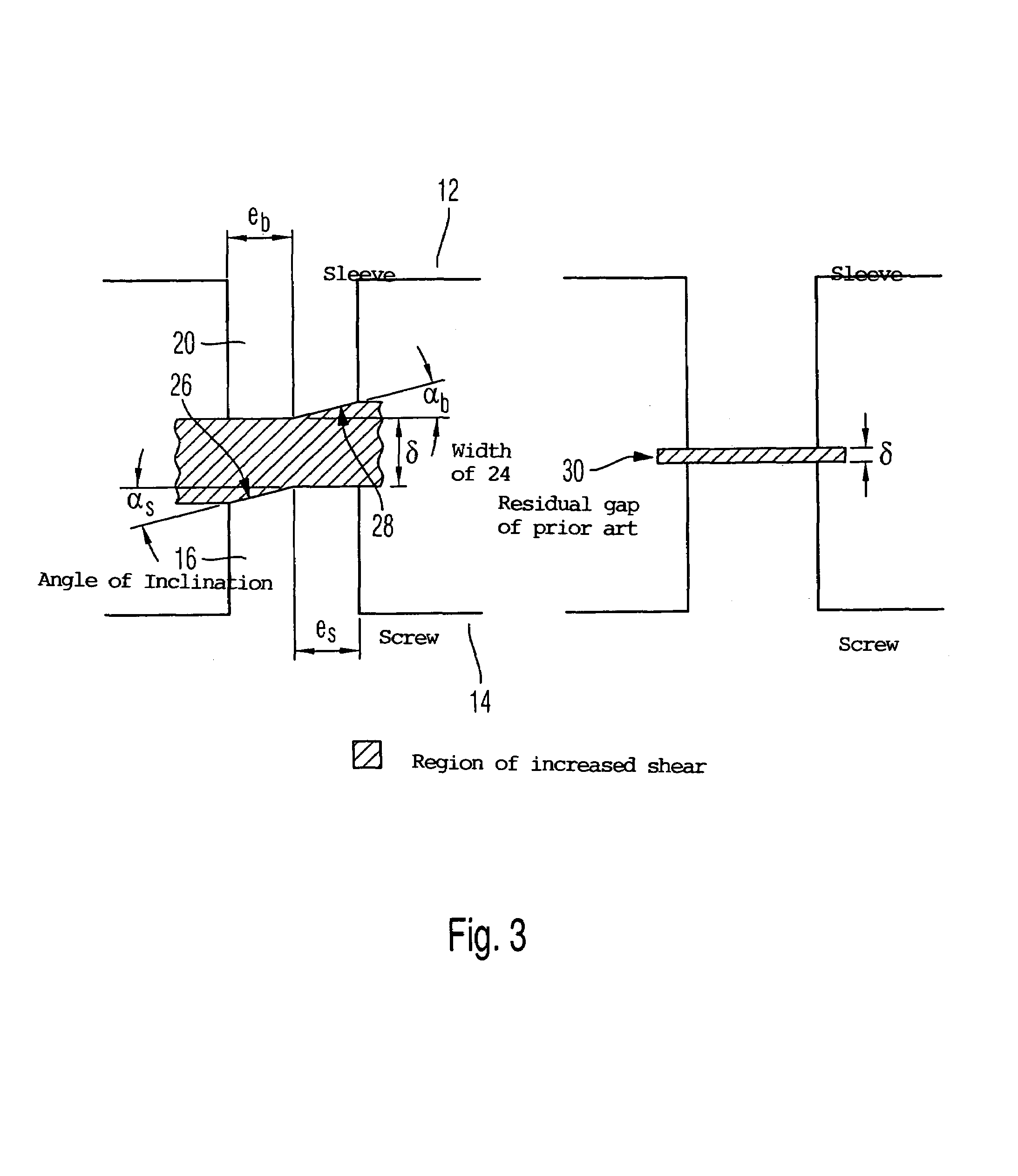
[0006]Pursuant to the invention, it is particularly expedient that, due to the provision of a transfer gap, a shear flow profile is produced that at the same length of the extruder offers a significantly improved homogenization. Due to the inventively induced elastic or shear flows, there is effected in a defined manner an improved thorough mixing, which makes the temperature level significantly comparable. Colder regions of the mixture can flow into the inventive width gap. The polymer chains that are present there are inclined to slide along one another and to thereby be heated in an efficient manner.
[0007]Pursuant to the invention, the retention time of the mixture in the extruder is clearly increased, whereby the length of the retention time can be controlled in a defined manner via the dimensioning of the inventive width gap.

Problems solved by technology

However, this unfortunately results in a reduction of the retention time of the extruded material in the extruder.
The discontinuous pitch in the screw lands of the transfer mixture region to this extent reduces the homogenization; the temperature behavior also becomes worse.

Method used


Image

  • Extruder
  • Extruder
  • Extruder

Examples


Embodiment Construction

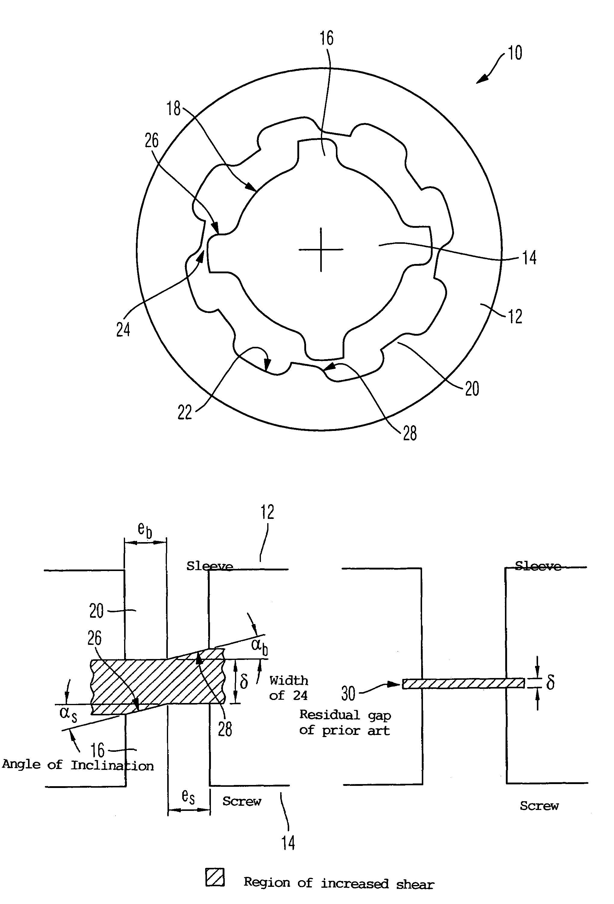
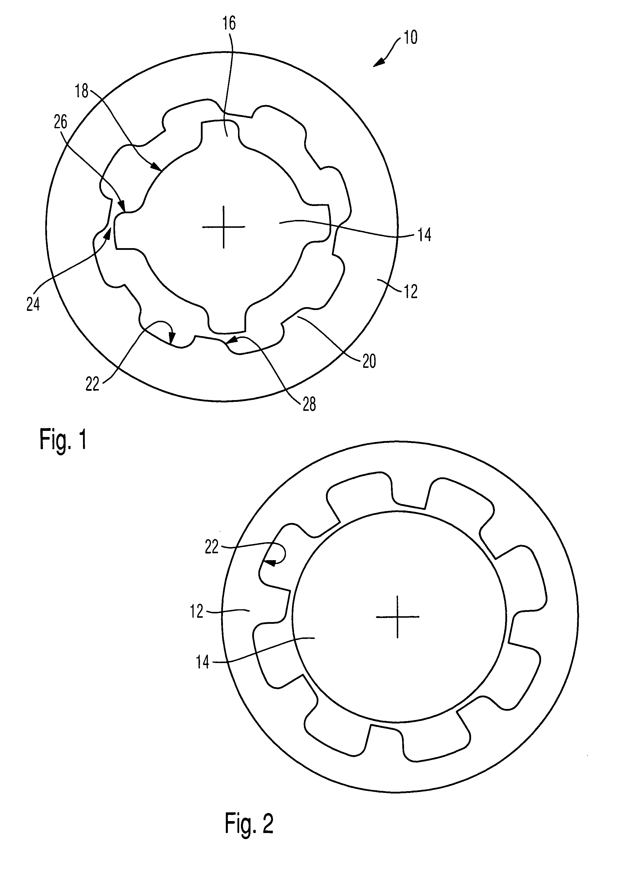
[0016]The extruder 10 illustrated in FIG. 1 has an extruder sleeve in which runs an extruder screw in a manner known per se. The cross-sectional view of FIG. 1 shows the transfer region. The extruder screw has ribs 16, between which extend flow channels 18. The extruder sleeve 12 also has ribs 20, between which extend flow channels 22. Pursuant to the invention, the width of the ribs 20 is increased, and in particular to a width that corresponds approximately to the width of the ribs 16 of the extruder worm or screw 14. In the illustrated embodiment, the width of the ridge is approximately half of the width of a flow channel 22.

[0017]Pursuant to the invention, there is furthermore formed between the ribs 16 and 20 a shear gap 24 that has a width of about 3% of the diameter of the screw. In combination with the lengthened or extended ridge width there thus results a shear gap 24 in which the extruded material is intensively and thoroughly mixed. It is to be understood that the width ...


PUM

PropertyMeasurementUnit
widthaaaaaaaaaa
angle of inclination αbaaaaaaaaaa
widthaaaaaaaaaa

Abstract

An extruder is provided having a transfer region that, in an extruder sleeve, is provided with ribs between which extend flow channels. Disposed opposite the sleeve flow channels are flow channels formed in the extruder screw, and the sum of the cross-sections of the flow channels, when viewed in the direction of extrusion, is shifted toward the sleeve and then toward the screw. The ribs (20) of the extrusion sleeve (12) at the ridges facing the screw (14) have a width that is at least one third, especially at least one half, and preferably approximately 80 to 100% of the width of the flow channels (22). Provided between the ridges of the ribs (20) of the extruder sleeve (12) and of the screw (14) is a gap (24) of more than 0.5%, in particular of about one percent of the diameter of the screw (14).

Description

BACKGROUND OF THE INVENTION[0001]The invention relates to an extruder having a transfer region which, in an extruder sleeve, has ribs between which extend flow channels, whereby opposite the sleeve flow channels, flow channels are formed in the extruder screw, and whereby the sum of the cross-sections of the flows channels, when viewed in the direction of extrusion, shift toward the sleeve and then toward the screw.[0002]Such an extruder is known, for example, from AT-E-40073B. It has a transfer region in which the material that is to be extruded is pressed out of the region of the extruder screw into threads provided in the extruder sleeve. By the transfer from the extruder screw into the region of the extruder sleeve, and back, the mixing of the starting materials is to be improved, which represents an important qualify feature of the extruded material. To avoid losses, the cross-sectional areas of the flow channels are precisely coordinated, and the extruder screw runs exactly in...

Claims


Application Information

Patent Timeline
Patent Type & Authority Patents(United States)
IPC IPC(8): B29B7/42B29C48/03B29C48/395B29C48/56
CPCB29C47/666B29C47/6043B29C47/38B29C47/0009B29C48/03B29C48/395B29C48/56B29C48/686
Inventor SKIBBA, OLAF
Owner A Z FORMEN & MASCHENBAU
Learn More