Perpendicular magnetic recording disk

a perpendicular magnetic and recording disk technology, applied in the field of magnetic recording disks, can solve the problems of limiting the use of perpendicular magnetic recording techniques in hdd applications, and reducing the noise level occurring with signal level increase, and achieving stable signal-to-noise ratio (snr) and reducing demagnetization energy.

Inactive Publication Date: 2006-09-05
SAMSUNG ELECTRONICS CO LTD
View PDF20 Cites 25 Cited by
  • Summary
  • Abstract
  • Description
  • Claims
  • Application Information

AI Technical Summary

Benefits of technology

[0016]To solve the above-described problems, it is an objective of the present invention to provide a perpendicular magnetic recording (PMR) disk with a single-layered structure or a pseudo double-layered structure including an intermediate soft magnetic layer to reduce the demagnetization energy of a perpendicular magnetic recording layer, in which amplification of a noise level occurring together with signal level increase is reduced with a stable signal-to-noise ratio (SNR) from magnetic domains.

Problems solved by technology

However, this decrease in size makes the data record domains susceptible to removal by thermal energy generated by operation of the HDD which is more dominant than magnetostatic energy from the data record domain.
However, the SPT perpendicular magnetic head also generates a demagnetization field stronger than the perpendicular field of the magnetic head, so the perpendicular magnetic field induced by the SPT head is insufficient for recording, thus limiting use of the perpendicular magnetic recording technique in HDD applications.
Thus, the effective perpendicular magnetic anisotropy energy of the perpendicular magnetic recording layer 13 is abruptly decreased with unsatisfactory high-density recording properties, thereby limiting HDD applications of the perpendicular magnetic recording technique.
However, the intermediate soft magnetic layer 26 is also likely to cause a random orientation of neighboring magnetic fields and results in additional noise (jitter), so the pseudo double-layer PMR disk has a higher noise level than the single-layer PMR disk.

Method used


Image

  • Perpendicular magnetic recording disk
  • Perpendicular magnetic recording disk
  • Perpendicular magnetic recording disk

Examples


example 1

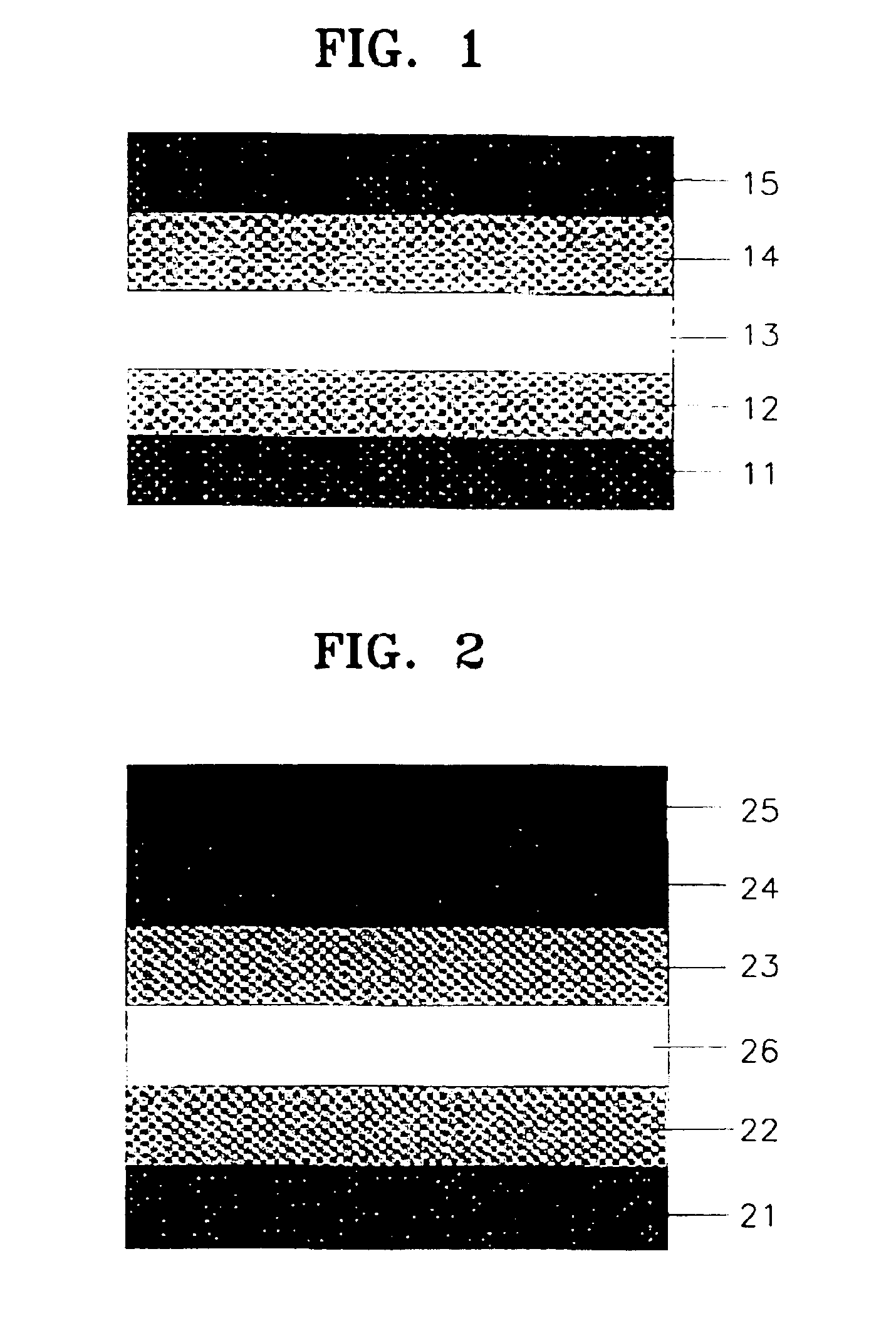
[0052]A Ti underlayer was deposited to a thickness of 50 nm on a glass substrate having a 650-nm thickness. A CoCr alloy PMR layer was formed on the Ti underlayer to a thickness of 35 nm, a carbon-based layer acting as a protective layer was formed thereon to a thickness of 10 nm, and a lubricant layer was formed thereon to a thickness of 2 nm, thereby resulting in a single-layer PMR disk.

example 2

[0053]A single-layer PMR disk was manufactured in the same manner as in Example 1 except that the thickness of the PMR layer was 20 nm.

example 3

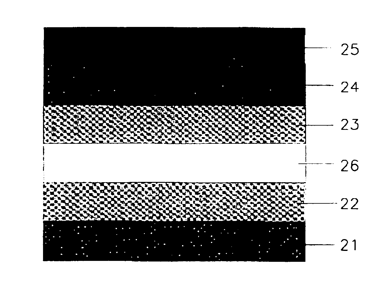
[0054]A Ti underlayer was deposited to a thickness of 50 nm on a glass substrate having a 650-nm thickness. An intermediate NiFe alloy soft magnetic layer was formed thereon to a thickness of 20 nm, and a CoCr alloy magnetic recording layer was formed as a PMR layer thereon to a thickness of 35 nm. Next, a carbon-based layer acting as a protective layer was formed thereon to a thickness of 10 nm, and a lubricant layer was formed thereon to a thickness of 2 nm, thereby resulting in a pseudo double-layer PMR disk.


PUM

PropertyMeasurementUnit
thicknessaaaaaaaaaa
thicknessaaaaaaaaaa
thicknessaaaaaaaaaa

Abstract

A perpendicular magnetic recording disk is provided. The perpendicular magnetic recording disk includes an underlayer between a substrate and a perpendicular magnetic recording layer for inducing perpendicular orientation of the perpendicular magnetic recording layer, the perpendicular magnetic recording layer having a thickness in the range where the ratio of perpendicular coercivity Hc to maximum perpendicular coercivity Ho decreases with reduced thickness of the perpendicular magnetic recording layer.

Description

[0001]Priority is claimed to Patent Application Number 2000-86269, filed in the Republic of Korea on Dec. 29, 2000, herein incorporated by reference.BACKGROUND OF THE INVENTION[0002]1. Field of the Invention[0003]The present invention relates to magnetic recording disks, and more particularly, to single-layer and pseudo double-layer perpendicular magnetic recording disks with microsized domains.[0004]2. Description of the Related Art[0005]In longitudinal magnetic recording (LMR) applied to hard disk drives (HDDs), a major external data storage device of computers, the size of a data record domain in a magnetic disk has decreased with microstructure as the need for high-density data recording increases. However, this decrease in size makes the data record domains susceptible to removal by thermal energy generated by operation of the HDD which is more dominant than magnetostatic energy from the data record domain. This is referred to as the super paramagnetic effect. To overcome the s...

Claims


Application Information

Patent Timeline
Patent Type & Authority Patents(United States)
IPC IPC(8): G11B5/66G11B5/64G11B5/62G11B5/667G11B5/72G11B5/725G11B5/73G11B5/738G11B5/82
CPCG11B5/64G11B5/656G11B5/667Y10T428/12861Y10T428/265Y10T428/24975Y10T428/28G11B5/7325G11B5/736G11B5/62
Inventor KIM, JAI-YOUNG
Owner SAMSUNG ELECTRONICS CO LTD
Why Eureka
Try Eureka