Time keeping apparatus and control method therefor
a timekeeping apparatus and timekeeping technology, applied in the field of timekeeping apparatus, can solve the problems of inability to know the correct time for several minutes, inaccurate time display, and problems of radio-controlled watches, and achieve the effect of knowing the current time more quickly
- Summary
- Abstract
- Description
- Claims
- Application Information
AI Technical Summary
Benefits of technology
Problems solved by technology
Method used
Image

Examples
first embodiment
[1] First Embodiment
[0030][1.1] Configuration of the First Embodiment
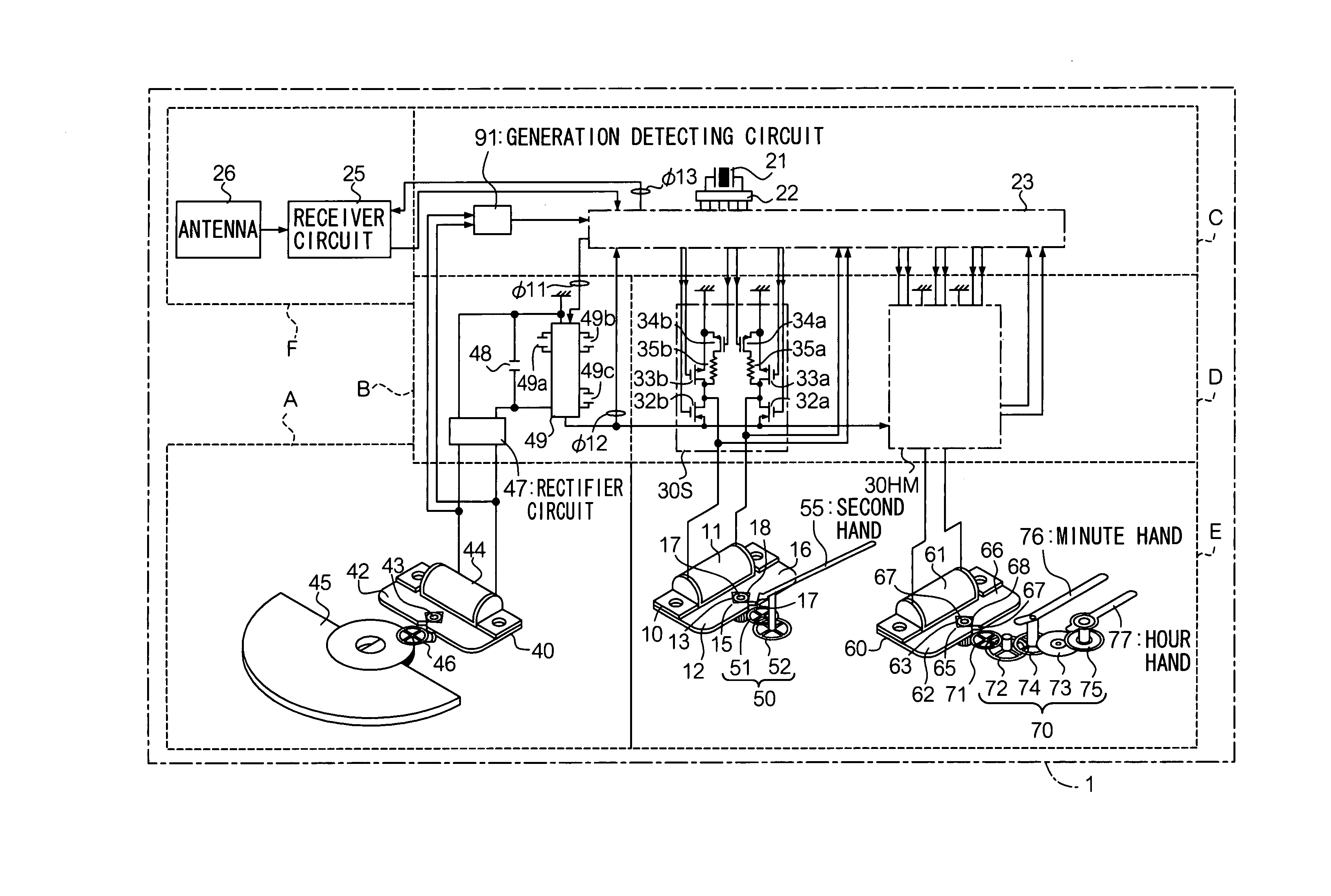
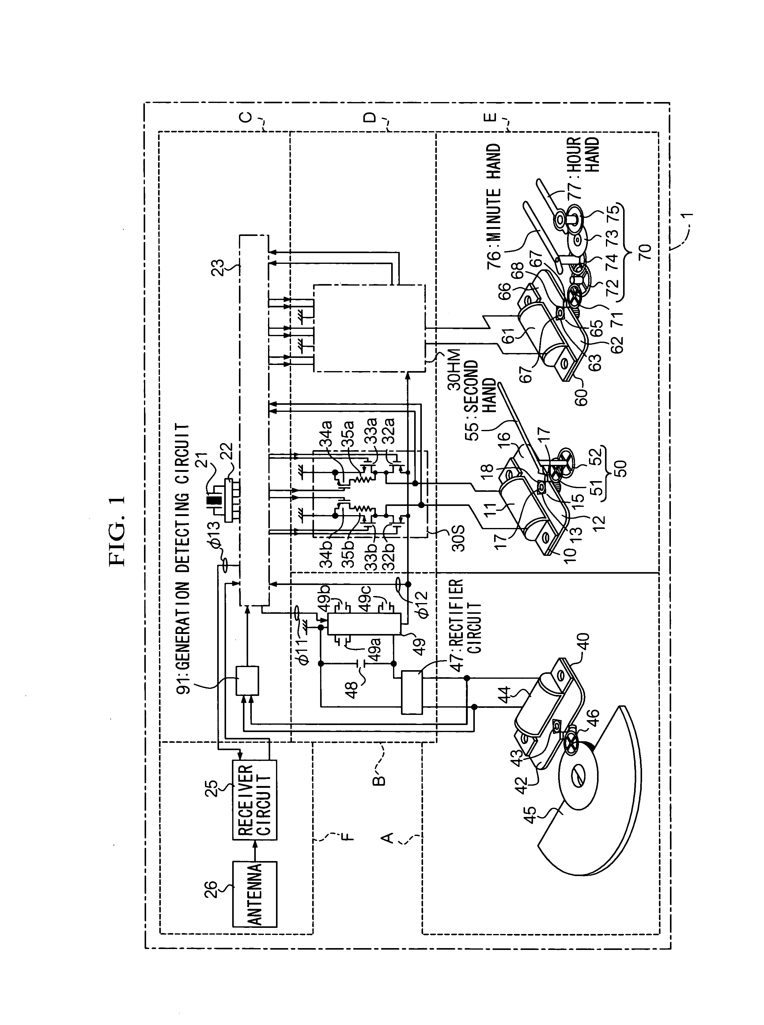
[0031]Referring to the drawings, a first embodiment of the present invention will be described. FIG. 1 shows a schematic configuration of a time keeping apparatus 1 according to the first embodiment of the present invention. The apparatus 1 is a wristwatch used with a belt connected to the watch body. A user winds the belt around one's own wrist.
[0032]The time keeping apparatus 1 essentially includes a power generation unit A for generating alternating current; a power source unit B for rectifying and boosting the alternating voltage from the power generation unit A, for storing the electricity, and for supplying each component with the power; a controller unit C for detecting a generation state of the power generation unit A and for controlling the apparatus based on the detected result; a hand drive mechanism E for moving hands by using an hour-and-minute motor 60 and a second motor 10; a drive unit D for driving...
second embodiment
[2] Second Embodiment
[0114]In contrast to the first embodiment of the present invention, in which actual location of the hands are not determined, a second embodiment of the present invention is with a mechanism by which actual location of the hand is determined in order to perform a current time display more correctly when switching from the power saving mode to the display mode.
[0115][2.1] Configuration of the Second Embodiment
[0116]FIG. 6 shows a configuration of a hand location determining element assembled in the hand movement mechanism of the time keeping apparatus of the second embodiment of the present invention. For the sake of easy understandings of the configuration of the hand location determining element, in FIG. 6, the hour hand, the minute hand, and the second hand are configured to be driven by one drives motor. The time keeping apparatus of the second embodiment of the present invention has the same configuration with the first embodiment shown in FIGS. 1 and 2 exce...
third embodiment
[3] Third Embodiment
[0149]In the third embodiment of the present invention, a solar cell is used for the power generation unit A. In FIG. 11, a schematic configuration of a time keeping apparatus of the third embodiment of the present invention is shown. In FIG. 11, each part identical to that in FIG. 1 has the same symbol as in FIG. 1, so its detailed explanation is omitted. The time keeping apparatus of the third embodiment of the present invention comprises a standard oscillation source 21, a controller circuit 23, a receiver circuit 25, a drive circuit 30, a countercurrent prevention diode 41, a large capacitance battery 48, a limiter circuit 81, a solar cell 89, and a generation detecting circuit 91″. The solar cell 89 converts light energy into electric energy. The countercurrent prevention diode 41 is used to prevent the stored charge in the battery 48 from flowing back.
[0150]With reference to FIG. 12, operation of the generation detecting circuit 91″ will be described. A sam...
PUM
 Abstract
Description
Claims
Application Information
 - R&D
- Intellectual Property
- Life Sciences
- Materials
- Tech Scout
- Unparalleled Data Quality
- Higher Quality Content
- 60% Fewer Hallucinations
Browse by: Latest US Patents, China's latest patents, Technical Efficacy Thesaurus, Application Domain, Technology Topic, Popular Technical Reports.
© 2025 PatSnap. All rights reserved.Legal|Privacy policy|Modern Slavery Act Transparency Statement|Sitemap|About US| Contact US: help@patsnap.com