Aggregate rate transparent LAN service for closed user groups over optical rings

a technology of optical rings and aggregate rates, applied in the field of data communication networks, can solve the problems of cumbersome accurate specification, high cost of required connectivity, cumbersome configuration and maintenance, etc., and achieve the effect of reducing the configuration burden on a customer

Active Publication Date: 2006-09-05
FUJITSU LTD
View PDF17 Cites 21 Cited by
  • Summary
  • Abstract
  • Description
  • Claims
  • Application Information

AI Technical Summary

Benefits of technology

[0007]In accordance with the present invention, apparatus and methods are disclosed for providing transparent LAN service in an optical ring network that reduces the configuration burden on a customer, specifically the burden of specifying data rates for a potentially large number of LAN source / destination pairs.
[0009]At each node of the ring, the use of a connected segment of the ring is monitored for both pass-through and locally-generated traffic of the CUG users on a per-CUG basis. When it is detected that use of the connected segment for a given CUG is approaching the proportion of ring data transmission capacity allocated to the CUG, an active one of the users of the CUG is sent a throttle message indicating that the user is to reduce its data transmission rate. This has the effect of limiting the CUG to its specified aggregate rate, without requiring any specification or monitoring of individual data rates among users of the CUG.

Problems solved by technology

The required connectivity can be expensive and difficult to configure and maintain.
In particular, it can be cumbersome to accurately specify the respective rates at which data is expected to be transferred between each of many source / destination pairs, a function that is required in the provisioning of frame relay and other data circuits.

Method used


Image

  • Aggregate rate transparent LAN service for closed user groups over optical rings
  • Aggregate rate transparent LAN service for closed user groups over optical rings
  • Aggregate rate transparent LAN service for closed user groups over optical rings

Examples


Embodiment Construction

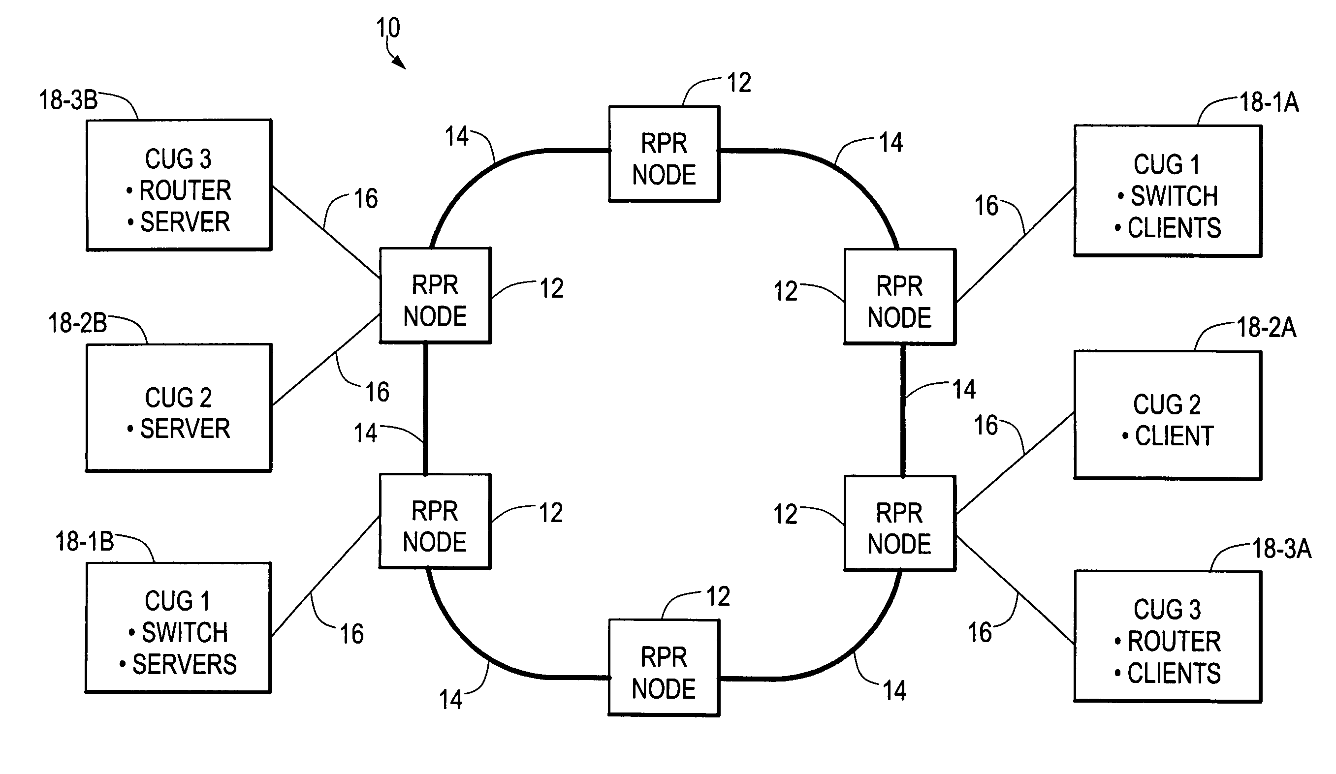
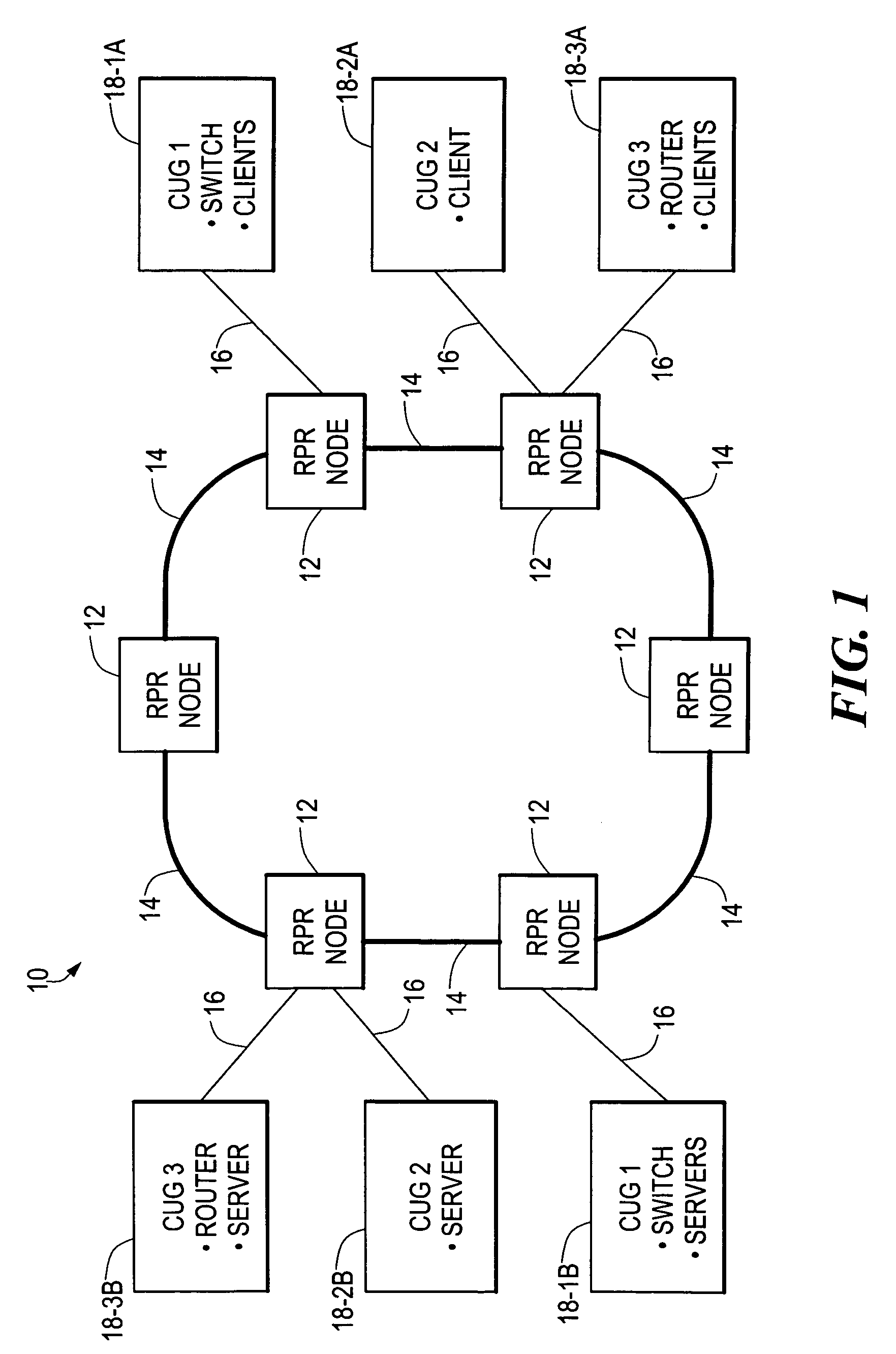
[0017]In FIG. 1, a resilient packet ring (RPR) optical network 10 includes a plurality of RPR nodes 12 interconnected by optical fiber ring segments 14. Various of the RPR nodes 12 are connected to customer links 16 via which customer traffic to be carried through the network 10 is provided. The links 16 are connected to different ports of these RPR nodes 12. The traffic and associated equipment of different customers are identified as belonging to different closed user groups (CUGs), which in the simplified network of FIG. 1 are shown as CUG 1, CUG 2, and CUG 3. CUG 1 includes a first collection 18-1A that includes a switch and one or more client machines, for example, and a second collection 18-1B that includes a switch and one or more server machines. Similarly, CUG 2 includes first and second collections 18-2A and 18-2B which respectively include a client machine and a server machine. CUG 3 includes a first collection 18-3A which includes a router and one or more client machines...


PUM


Abstract

A ring network provides transparent local area network (LAN) service by allocating respective proportions of data transmission capacity of the ring to different closed user groups (CUGs), each including a plurality of LAN clients. At each node of the ring, the use of a connected segment of the ring is monitored for both pass-through and locally-generated traffic by the LAN clients on a per-CUG basis. When it is detected that use of the connected segment for a CUG is approaching the allocated proportion, an active LAN client of the CUG is selected and sent a throttle message indicating that the LAN client is to reduce its data transmission rate. Rate monitoring for is accomplished using a “leaky bucket” mechanism. A “rate cache” identifying the active senders and their transmission rates can also be used in selecting a LAN client for receiving the throttle message.

Description

CROSS REFERENCE TO RELATED APPLICATIONS[0001]NoneSTATEMENT REGARDING FEDERALLY SPONSORED RESEARCH OR DEVELOPMENT[0002]Not ApplicableBACKGROUND OF THE INVENTION[0003]The present invention is related to the field of data communications networks, and more particularly to networks providing transparent local area network (LAN) service.[0004]Wide-area data communications networks or WANs can be used to provide so-called “transparent LAN service” among devices attached to geographically separated LAN segments. Transparent LAN service effectively hides the underlying WAN network from the devices, and thus enables the devices to communicate using only their native LAN protocol. Transparent LAN service can provide several important benefits such as backwards compatibility while providing fast connection speeds and lower operating costs. Newer WAN networking equipment can successfully interoperate with devices having only LAN interfaces, and customer investments in LAN equipment can be protec...

Claims


Application Information

Patent Timeline
Patent Type & Authority Patents(United States)
IPC IPC(8): H04L12/26H04J3/14H04L1/00H04L12/46H04L12/56
CPCH04L1/0025H04L47/11H04L47/13H04L47/263H04L47/10H04J3/14H04L1/0002Y02B60/31Y02D30/50
Inventor SULTAN, ROBERTSAHAI, AJAYPANDHI, SUSHILYANG, ZUBAO
Owner FUJITSU LTD
Why Eureka
Try Eureka