Phase comparator and method of controlling power saving operation of the same, and semiconductor integrated circuit

a technology of phase comparator and power saving operation, which is applied in the direction of oscillator comparator circuit, pulse automatic control, pulse technique, etc., can solve the problems of constant phase difference between the reference signal frar and the inverted signal xrpar, and the power saving state might be wrongly cancelled

a technology of phase comparator and power saving operation, which is applied in the direction of oscillator comparator circuit, pulse automatic control, pulse technique, etc., can solve the problems of constant phase difference between the reference signal frar and the inverted signal xrpar, and the power saving state might be wrongly cancelled

US7103132B1Inactive Publication Date: 2006-09-05MONTEREY RES LLC

Image

  • Phase comparator and method of controlling power saving operation of the same, and semiconductor integrated circuit
  • Phase comparator and method of controlling power saving operation of the same, and semiconductor integrated circuit
  • Phase comparator and method of controlling power saving operation of the same, and semiconductor integrated circuit

Examples


first embodiment

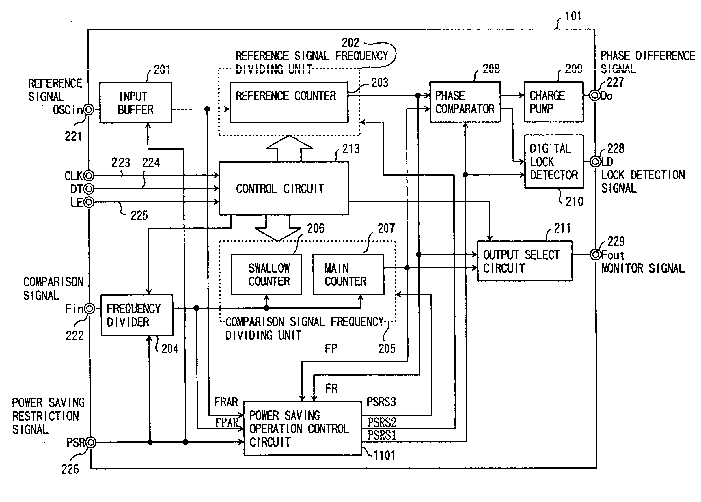
[0069]FIG. 11 shows a phase comparator unit 101 of the present invention. In this figure, the same components as in FIG. 2 are denoted by the same reference numerals. A power saving operation control circuit 1101 of this embodiment generates internal power saving restriction signals PSRS1, PSRS2, and PSRS3, based on the reference signal FRAR, the output signal FPAR of the frequency divider 204, the output signal FR of the reference signal frequency dividing unit 202, and the output signal FP of the comparison signal frequency dividing unit 205.

[0070]FIG. 12 shows the power saving operation control circuit 1101 of the present invention. When a power saving restriction signal (PSR) 1231 is low, the power saving operation is performed. When the power saving restriction signal 1231 becomes high, the power saving state is canceled. The power saving restriction signal 1231 is supplied to the D-input terminal and the reset terminal RESET of a D-flip-flop 1201, the reset terminal RESET of a...

second embodiment

[0080]FIG. 15 shows a transmitter-receiver in accordance with the present invention.

[0081]At the time of reception, following a program stored in a PROM 1515, a microcomputer 1512 captures a receiving channel designated by a KEY 1514. The microcomputer 1512 then sets a frequency of a PLL frequency synthesizer 1505 of a reception unit of the present invention. The setting of the frequency is carried out by setting the frequency dividing rates of the reference counter of the reference signal frequency dividing unit, and the swallow counter and the main counter of the comparison signal frequency dividing unit in the phase comparator unit. The receiving channel designated by the KEY 1514 and a receiving condition are displayed on a liquid crystal display (LCD) 1513. An antenna 1501 receiving a reception signal sends the reception signal to an antenna switch 1502. The antenna switch 1502 sends a signal from the antenna 1501 to the side A, when the transmitter-receiver is in a receiving s...


PUM


Abstract

A power saving operation control method and device for a phase comparator unit are provided. The control device includes: a reference signal frequency dividing unit which divides the frequency of a reference signal to generate a reference frequency divided signal; a comparison signal frequency unit which divides an input signal to generate a comparison frequency divided signal; a phase comparator which compares the phases of the reference frequency divided signal and the comparison frequency divided signal; a canceling signal generator which generates a power saving state canceling signal in accordance with the reference frequency divided signal and the comparison frequency divided signal; a first initializing signal generator which generates a first initializing signal for initializing the reference signal frequency dividing unit in accordance with the power saving state canceling signal; and a second initializing signal generator which generates a second initializing signal for initializing the comparison signal frequency dividing unit in accordance with the power saving state canceling signal.

Description

BACKGROUND OF THE INVENTION[0001]1. Field of the Invention[0002]The present invention generally relates to PLL frequency synthesizers, and, more particularly, to a method of controlling a phase comparator for performing a power saving operation and a semiconductor circuit.[0003]2. Description of the Related Art[0004]FIG. 1 is a block diagram of a conventional PLL frequency synthesizer. The PLL frequency synthesizer comprises a voltage control oscillator 102, a phase comparator unit 101, a low pass filter 106, and a microcomputer 108. The phase comparator unit 101 receives a comparison signal through an input terminal Fin and a reference signal through an input terminal OSCin. A capacitor 105 removes the DC component from the output of the voltage control oscillator 102 to obtain the comparison signal. A capacitor 104 removes the DC component from a reference frequency signal 103 to obtain the reference signal. The frequencies of the comparison signal and the reference signal are div...

Claims


Application Information

Patent Timeline
05 Sep 2006
Publication
US7103132B1
IPC
H03D3/24; H03L7/26; H03D13/00; H03K23/64; H03L7/085; H03L7/18; H03L7/193; H03L7/199
CPC
H03D13/00; H03L7/199; H03L7/193; H03K23/64; H03D2200/0084
Inventors
BABA, HIROSHI