Architecture for an optical satellite communication network

a communication network and optical satellite technology, applied in the field of space and communications satellites, can solve the problems of increasing the scarce remaining slots, consuming a significant amount of electric power for high speed switching electronics, and limited growth to higher frequencies, so as to maximize the overall data handling capacity, and maximize the maximum utilization of rf ground channels

Inactive Publication Date: 2006-09-05
HUGHES ELECTRONICS
View PDF32 Cites 41 Cited by
  • Summary
  • Abstract
  • Description
  • Claims
  • Application Information

AI Technical Summary

Benefits of technology

[0015]The advantage of the invention is in retaining the benefits of passive optical routing with a minimal number of required optical carriers. As a result of passive optical routing, the electronic switch on board a satellite is relieved of routing the relayed data traffic, thereby maximizing the overall data handling capacity. This may also conserve the overall system power consumption and weight. In addition, the network with passive optical routing is transparent to protocols in the sense that intermediate satellites do not have to understand the nature of the traffic (e.g., broadcast

Problems solved by technology

As a result, the government has been auctioning the increasingly scarce remaining slots.
Growth to higher frequencies is limited by difficult problems in technology and propagation.
High speed switching electronics consume a significant amount of electric power which is always at a premium on board of satell

Method used


Image

  • Architecture for an optical satellite communication network
  • Architecture for an optical satellite communication network
  • Architecture for an optical satellite communication network

Examples


Embodiment Construction

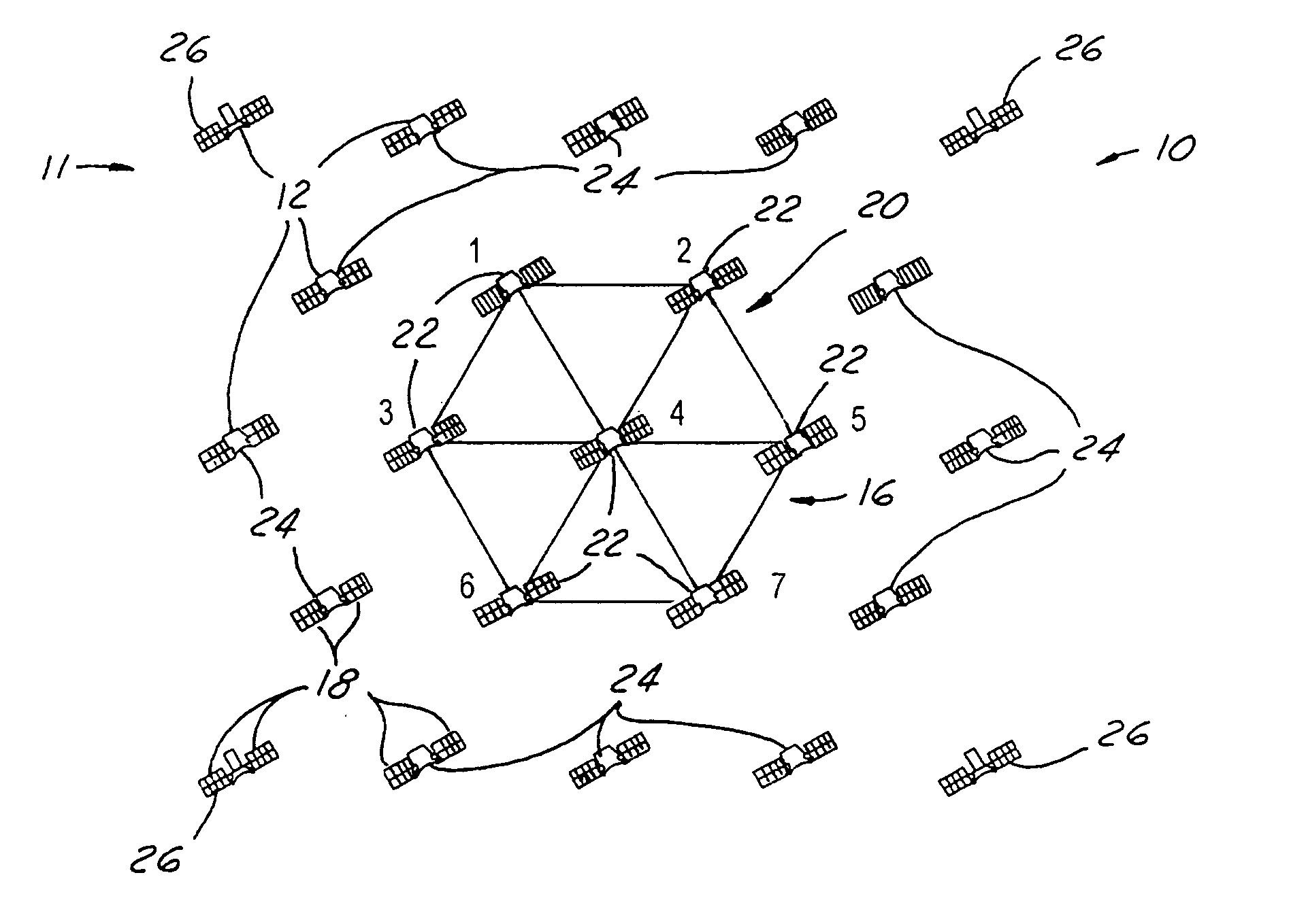
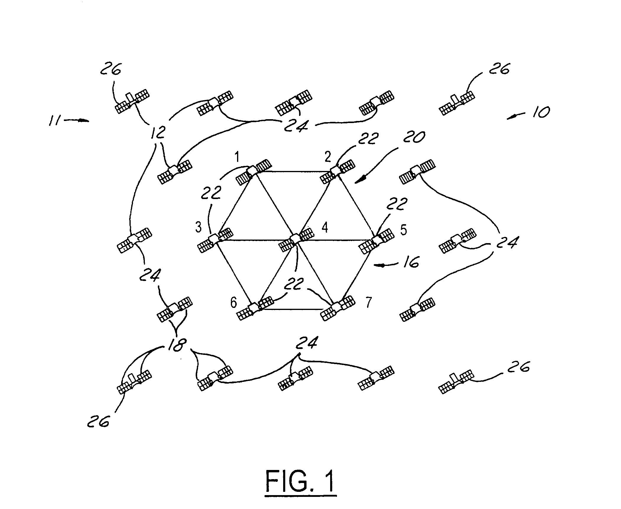
[0022]Referring now to FIG. 1, a communication system 10 includes satellite constellation 11 that has a plurality of satellites 12 orbiting the earth. Although not illustrated satellites 12 communicate with other satellites through an optical link and with ground stations (not shown) in a conventional manner. Although this invention may be used for other satellites in other types of orbits, this invention is particularly suitable for satellites in LEOs or MEOs. Due to the constant movement of the satellites, FIG. 1 is a snapshot of a portion of constellation 11.

[0023]Satellites 12 form a network 16. Network 16 is essentially a local area network (LAN) within satellite constellation 11. Each satellite 12 receives and transmits radio frequency (RF) communications to earth by way of antennas 18. As will be further described below, each satellite 12 may communicate with an adjacent satellite in network 16 using optical signals. Because satellites 12 are spaced apart with respect to the ...


PUM


Abstract

A satellite constellation has a plurality of satellites. Each of the satellites has an RF ground link for communicating with a ground station and an optical link for communication with at least one of the plurality of satellites. Each of the satellites has a reconfigurable optical transmitter for sending and receiving data streams. Each reconfigurable optical transmitter has a first optical carrier associated therewith and a reconfigurable optical receiver. The plurality of satellites is arranged to have a first subset of satellites. The first subset of satellites is configured to communicate. The plurality of satellites is reconfigured to have a second subset of satellites having at least one different satellites than that of said first subset. The second subset supercedes the first subset. The second subset of satellites is configured to communicate. Various subset around the globe may form local area networks. The local area networks are preferably optically coupled to form a wide area network.

Description

TECHNICAL FIELD[0001]The present invention relates to space and communications satellites, and more particularly, to a communication system to interconnect satellites.BACKGROUND ART[0002]Satellites in geostationary orbits (GSO's) have been widely preferred because of the economic advantages afforded by such orbits. In a geostationary orbit, a satellite traveling above the earth's equator, in the same direction as that in which the earth is rotating, and at the same angular velocity, appears stationary relative to a point on the earth. These satellites are always “in view” at all locations within their service areas, so their utilization efficiency is effectively one-hundred percent. Antennas on earth need be aimed at a GSO satellite only once; no tracking system is required.[0003]Coordination between GSOs and with terrestrial services is facilitated by governmental allocation of designated “slots” angularly spaced according to service type.[0004]Given the desirability of geostationa...

Claims


Application Information

Patent Timeline
IPC IPC(8): H04B10/00
CPCH04B10/118
Inventor IONOV, STANISLAV I.VALLEY, GEORGE C.ACAMPORA, ANTHONY S.
Owner HUGHES ELECTRONICS
Why Eureka
Try Eureka