
Device with passive receiver

Active Publication Date: 2006-09-05
KONINKLIJKE PHILIPS ELECTRONICS NV
View PDF102 Cites 236 Cited by
  • Summary
  • Abstract
  • Description
  • Claims
  • Application Information

AI Technical Summary

Benefits of technology

[0009]A significant advantage of the present invention is that it provides non-contact, non-line-of-sight operation that can activate a transceiver that is powered-down.
[0010]This summary is intended to provide a brief overview of some of the embodiments of the present system, and is not intended in an exclusive or exhaustive sense, and the scope of the invention is to be determined by the attached claims and their equivalents.
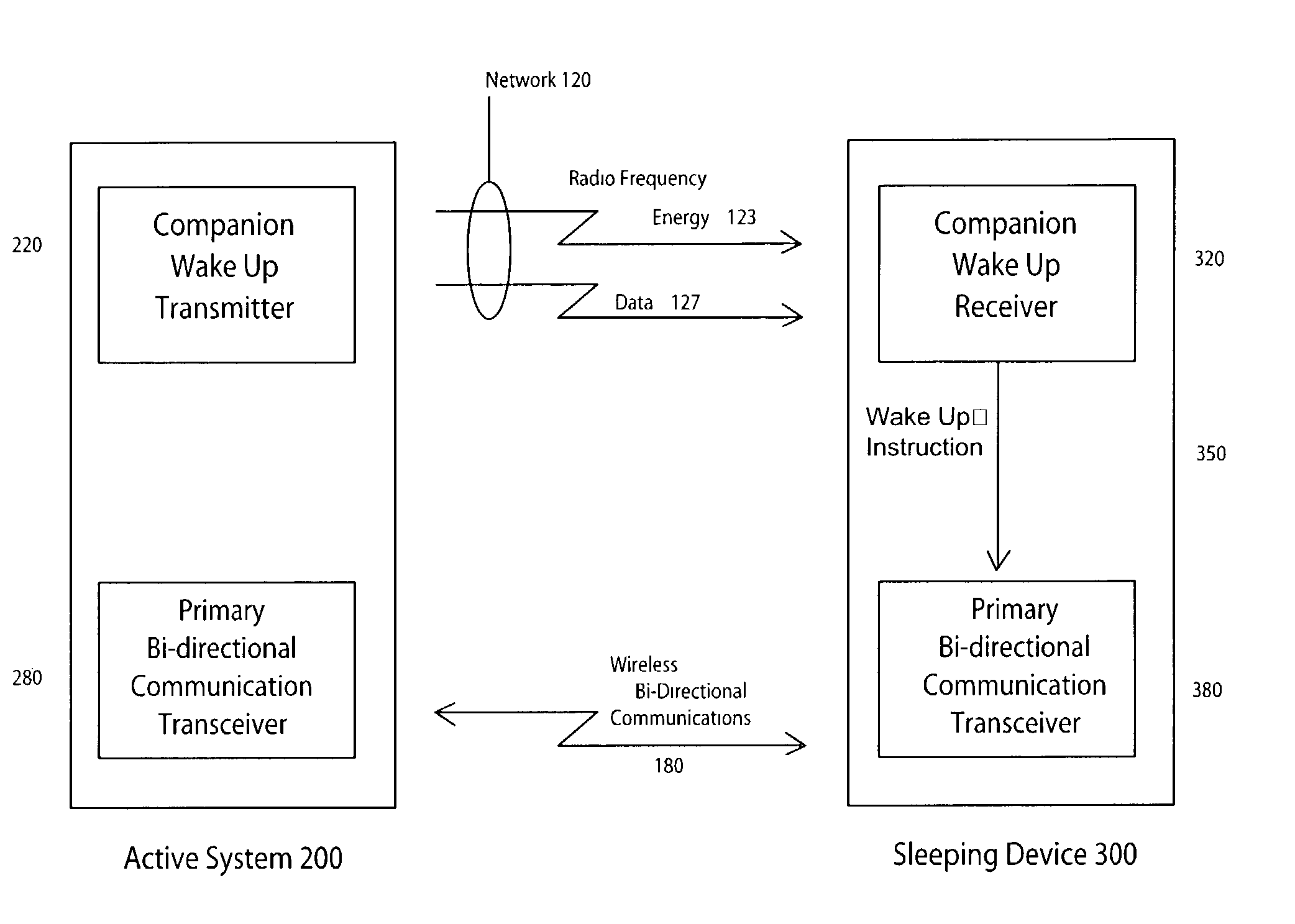
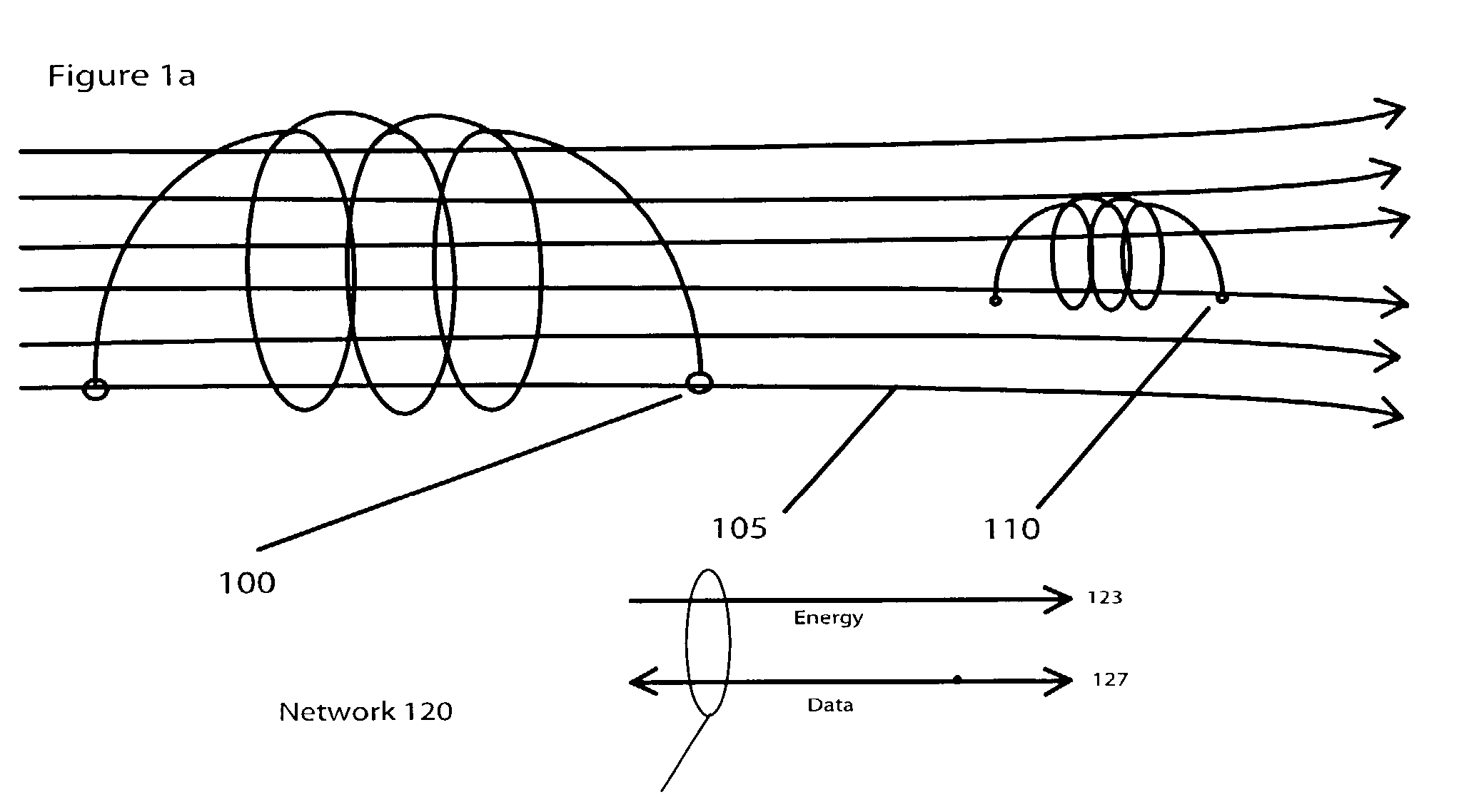
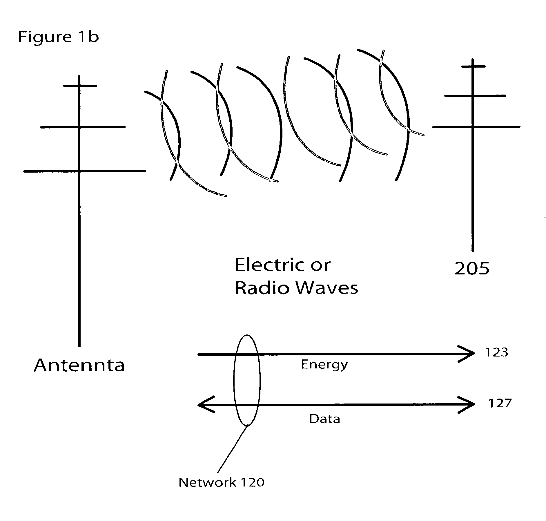
[0011]In one embodiment disclosed herein is a method to use radio frequency energy to activate a primary transceiver that is normally inactive or powered off. An electromagnetic field is used to excite a nearby antenna and its associated companion receiver or transceiver and optionally its processing and memory circuits. Based upon the energy received and data that may be carried in the electromagnetic energy field by this companion communications system, another more robust primary transceiver system is activated for communications. In addition, the data sent and received in the companion system may carry identification information, security checks, or instructions.

Problems solved by technology

There are at least two problems with this method.
Second, some wireless networks require acquisition time for the network to synchronize, handshake, verify security protocols, etc.
This can be a time consuming and by correlation, a power consuming process.
For many devices that may be associated with wireless networks, this is an unacceptable solution because the power draw cannot be supported.

Method used


Image

  • Device with passive receiver
  • Device with passive receiver
  • Device with passive receiver

Examples


first embodiment

[0094]In a first embodiment, the sleeping device 300 may be incorporated into a sensor of a security system, for example, a glass breakage sensor. To conserve power, the sensor's wireless communications transceiver 380 is normally powered down, while the sensor itself and its processor draw enough power to respond to a breakage event. Upon detecting glass breakage, the sensor / processor module can power up the wireless communications transceiver 380 and use it to transmit signals associated with the detected event to a central control panel. In addition, the central control panel may query the sensor as to its status by sending a wake-up signal to the sensor's wake-up receiver 320. When the wake-up receiver 320 detects the radio frequency energy of the query, the receiver 320 can power up the wireless communications transceiver 380, which can then send status data to the central control panel.

second embodiment

[0095]In a second embodiment, the sleeping device 300 may be incorporated into an implanted medical device such as a combination heart monitor / defibrillator that is implanted in a person's body. The monitor / defibrillator draws enough power to monitor the heartbeat and to respond to fibrillation by beginning defibrillation, but the monitor / defibrillator's wireless communications transceiver 380 is normally powered down to conserve power. However, the battery of the monitor / defibrillator has a limited lifetime, and it is necessary for a medical professional to query the status of the battery periodically. To avoid subjecting the patient to additional surgery, a reading device may send a wake-up signal to the wake-up receiver 320 of the sleeping device 300. The receiver 320 can then power up the wireless communications transceiver 380, which in turn can send data on the battery's charge to the reading device. Similar processes can be used to read electrocardiogram signals, program the ...


PUM


Abstract

A wireless communications apparatus includes a wake-up receiver adapted to receive a wake-up signal and an initially powered-off, sleeping wireless communications transceiver. When the wake-up receiver receives the wake-up signal, it can in turn power on the wireless communications transceiver. In another aspect, the invention includes an apparatus for sending a wake-up signal to the wake-up receiver. The wake-up transmitter and the wake-up receiver can communicate via a variety of wireless communications protocols, including the BLUETOOTH™ standard.

Description

[0001]The present application is a continuation-in-part of co-pending U.S. patent application Ser. No. 10 / 165,624, filed Jun. 7, 2002, and claims the benefit of International Application No. PCT / US01 / 18734, filed Jun. 8, 2001.FIELD OF THE INVENTION[0002]The present invention relates generally to wireless networks and in particular to an apparatus and method to activate a wireless device that is powered off.BACKGROUND OF THE INVENTION[0003]Wireless networks may be used to transmit signals from devices that are only activated rarely. For example, a sensor detecting glass-breakage in a security alarm system may only rarely be activated. In such a design, the system may continuously power the sensor and processor to monitor for glass breakage while the associated wireless transceiver may be powered-down to save battery power. Upon detecting glass breakage, the sensor / processor module can power up the associated wireless transceiver and use it to transmit signals associated with the dete...

Claims


Application Information

Patent Timeline
IPC IPC(8): H04B1/16A61M5/20
CPCA61M5/2033H04W52/0229A61M5/14276A61M2005/2013A61M2205/3569A61M2205/8212A61N1/37276A61M2205/3523Y02D30/70
Inventor MENARD, RAYMOND J.
Owner KONINKLIJKE PHILIPS ELECTRONICS NV
Learn More