
Automatic distance control method and system for motor vehicles

a technology of automatic distance control and motor vehicles, applied in simultaneous traffic control systems, process and machine control, instruments, etc., can solve the problems of utilizing the full braking force available, limiting the maximum deceleration possible to about 2 m/s

Active Publication Date: 2006-09-05
WABCO EURO BVBA SPRL
View PDF7 Cites 32 Cited by
  • Summary
  • Abstract
  • Description
  • Claims
  • Application Information

AI Technical Summary

Benefits of technology

[0006]Generally speaking, in accordance with the present invention, an improved automatic vehicle distance-control method and system are provided which avoid disadvantages associated with conventional methods and systems.
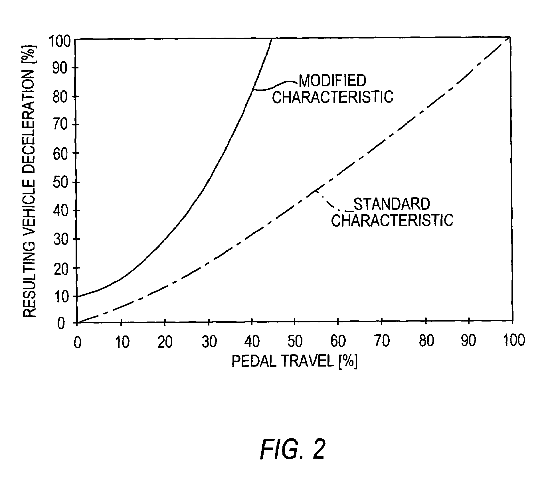
[0007]According to the present invention, a vehicle distance-control device is designed such that it automatically recognizes a critical situation in which the maximum deceleration attainable by the vehicle distance-control system is insufficient to prevent the danger of a collision, warns the driver and simultaneously modifies the brake pedal characteristic (i.e., the relationship between brake pedal displacement and applied brake pressure) such that a slight actuating pressure, such as a “tap” on the brake pedal by the driver, is sufficient to trigger braking with increased or full brake pressure.
[0009]According to the present invention, however, the braking time, or in other words the time needed in order to bring the vehicle to the desired lower speed or to a stop, is simultaneously shortened, and so the danger of a collision is correspondingly diminished. The present invention has the advantage that the danger potential is recognized by a control device, which then automatically initiates partial braking. By this, the driver is always made aware of the danger. The present invention provides that full braking can be initiated independently of actuating speed, even if such actuation is hesitant.
[0010]Accordingly, it is an object of the present invention to provide an improved automatic vehicle distance-control method and system that enable full braking to be initiated independently of actuating speed (even if hesitant) to avoid the danger of collision.

Problems solved by technology

Typically, in such conventional systems, the maximum deceleration possible is limited to about 2 m / s2.
Tests have shown, however, that in some cases drivers faced with emergency situations do not depress the brake pedal fully and thus do not utilize the full braking force available.

Method used


Image

  • Automatic distance control method and system for motor vehicles
  • Automatic distance control method and system for motor vehicles
  • Automatic distance control method and system for motor vehicles

Examples


Embodiment Construction

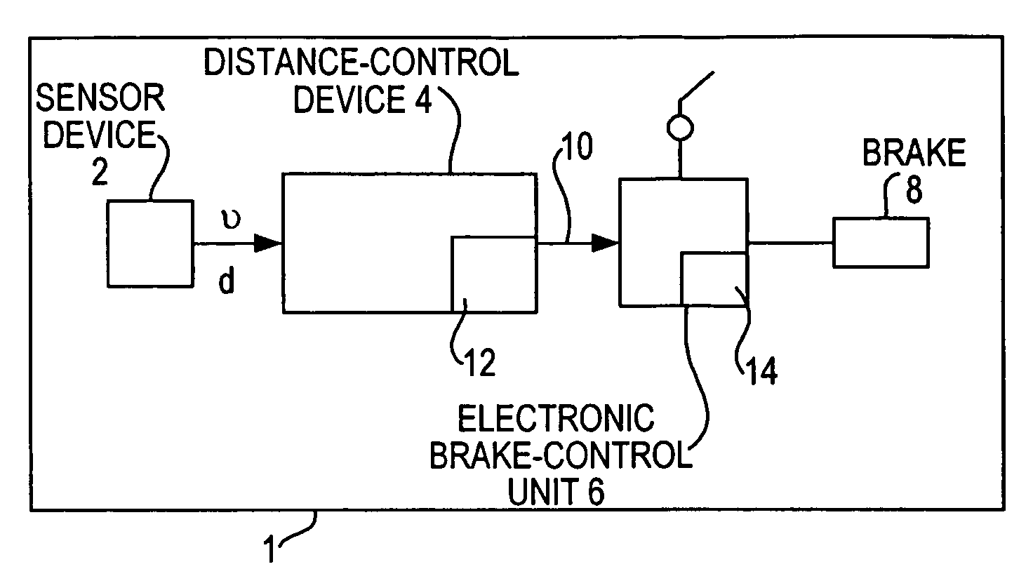
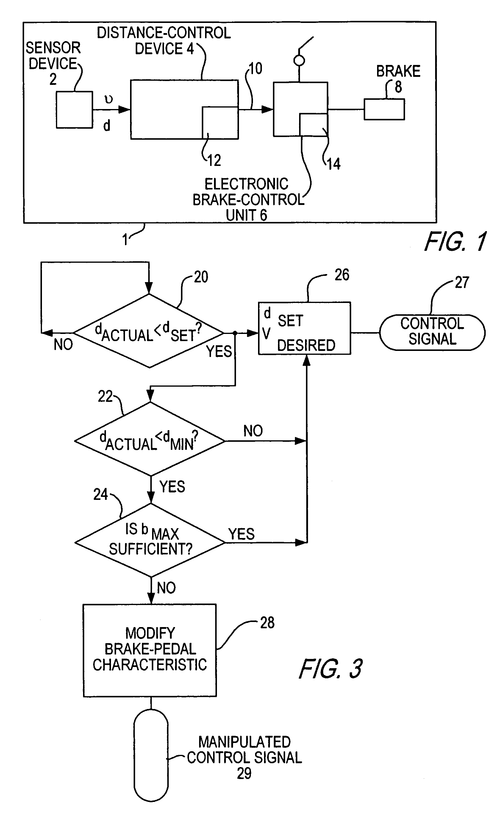
[0017]Referring now to the drawing figures, FIG. 1 is a block diagram of a vehicle 1 equipped with an automatic vehicle distance-control system according to a preferred embodiment of the present invention. A sensor device 2 transmits distance signals d and speed signals v to a distance-control device 4. Distance-control device 4 evaluates these signals according to a computer program and calculates the distances to a lead vehicle as well as the speed thereof.

[0018]Vehicle 1 also includes an electronically controllable brake system having an electronic brake-control unit 6, which controls at least one vehicle brake 8 as a function of a braking command from the driver as produced by a brake-value generator (such as a brake pedal) actuated by the driver. Brake-control unit 6 is electrically connected via a data line 10 to distance-control device 4. Via data line 10, distance-control device 4 transmits a brake-ready signal, a brake-demand signal or further signals as necessary. Brake-co...


PUM


Abstract

A method and system for automatic control of the distance between a vehicle to be controlled and a lead vehicle. The vehicle to be controlled is equipped with a distance-control device having a distance sensor and a brake device with a brake pedal. The distance-control device controls the speed of the controlled vehicle by delivering a brake-actuating signal to the brake device in such a way that the distance between the vehicles does not become shorter than a predefined distance, the distance-control device also generating a warning signal to the driver if the distance becomes shorter than the predefined distance. The distance-control device changes the brake pedal characteristic in such a way that the brake pedal travel required for injection of increased brake pressure is minimized if a criterion that indicates a danger of collision is present.

Description

BACKGROUND OF THE INVENTION[0001]The present invention is directed generally to an automatic distance-control method and system for motor vehicles.[0002]In conventional vehicle distance-control systems concerned with maintaining a safe distance between a controlled or following vehicle and a lead vehicle (such as, for example, distance-control systems of the type described in DE 44 37 678 A1 and DE 199 51 423 A1), a measuring device acquires information about the distance from the controlled or following vehicle to the lead vehicle and uses the information to control the speed of the controlled vehicle such that the distance to the lead vehicle does not become shorter than a predefined set distance or a speed-dependent set distance. Such speed regulation can be achieved by intervention of a distance-control device in the brake system or engine controller. Typically, in such conventional systems, the maximum deceleration possible is limited to about 2 m / s2.[0003]In situations in whic...

Claims


Application Information

Patent Timeline
IPC IPC(8): G08G1/16G08G7/00B60K31/00B60K31/18B60T7/12B60W30/08B60W30/16
CPCB60K31/0008B60K31/18B60W30/16B60T7/12G08G1/16B60W30/09G08G1/166B60W2050/143B60T7/22G08G1/163
Inventor ZIELKE, FRANK
Owner WABCO EURO BVBA SPRL
Learn More