
System and method for leveraging independent innovation in entertainment content and graphics hardware

Inactive Publication Date: 2006-09-05
ACTIVISION PUBLISHING
View PDF10 Cites 142 Cited by
  • Summary
  • Abstract
  • Description
  • Claims
  • Application Information

AI Technical Summary

Benefits of technology

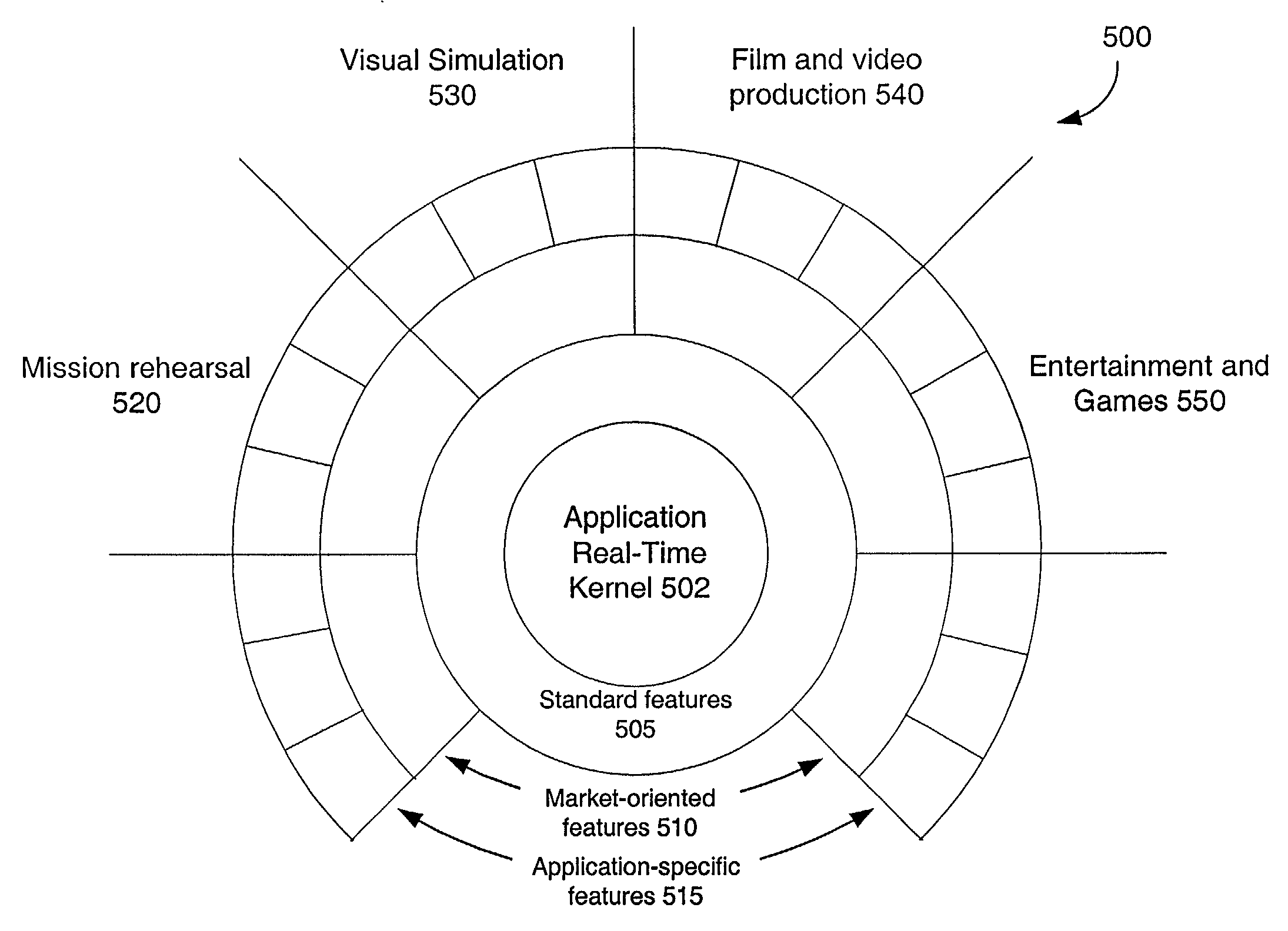
[0025]An innovative software architecture, the Graphical Application Platform (GAP) is presented. In one embodiment, the GAP includes an application real-time kernel (ARK) and components containing executable blocks of logic. The GAP builds on image generator, workstation, and scene graph success by extending the concepts of platform and framework into the real-time graphics domain—bridging the gap between image generation concerns and contemporary hardware and software

Problems solved by technology

However, advances of software technology can lead to the discovery of new barriers.
When extended to allow application developers to attach callback functions or redefine scene graph elements, however, a problem emerges.
This “tree decoration” metaphor converts a scene graph into an expression tree with critical but unstated order dependencies, surreptitiously changing the meaning of scene graph traversal with the result that any two or more extensions are likely to be incompatible.
It is difficult if not impossible for separate developers to build independent features that can be merged into the common scene graph due to extension model semantic conflicts.
This leads integrators to develop their own visual simulation run-time environments since they lack a framework for integrating sub-components from independent software providers, resulting in multiple versions of the same base features.
This troubles technical evaluators, who may know that a machine is capable of a feature, but cannot know if a particular bidder will implement it as desired—and there is no way to replace a weak implementation in one program with a strong implementation from another.
Difficulties in Integration.
Even though the last 20% of the integration task seemingly requires 80% of the time and expense, there are few tools to help.
Scene graphs are partially responsible, as extension model problems surface at integration time (when different sub-components first operate together) and developers cannot profile, understand, or modify the inner-workings of the scene graph.
If testing reveals that a simulator “almost always” runs at frame rate, the developer is typically at a loss to know what the scene graph is doing differently to cause frame extension.
This same information must also appear in the scene graph in an opaque form due to its autonomous nature, which requires duplication of application state between the two with problems in synchronization and updating.
These problems are signs of an inherent structural mismatch rather than a flaw of scene graph implementations.
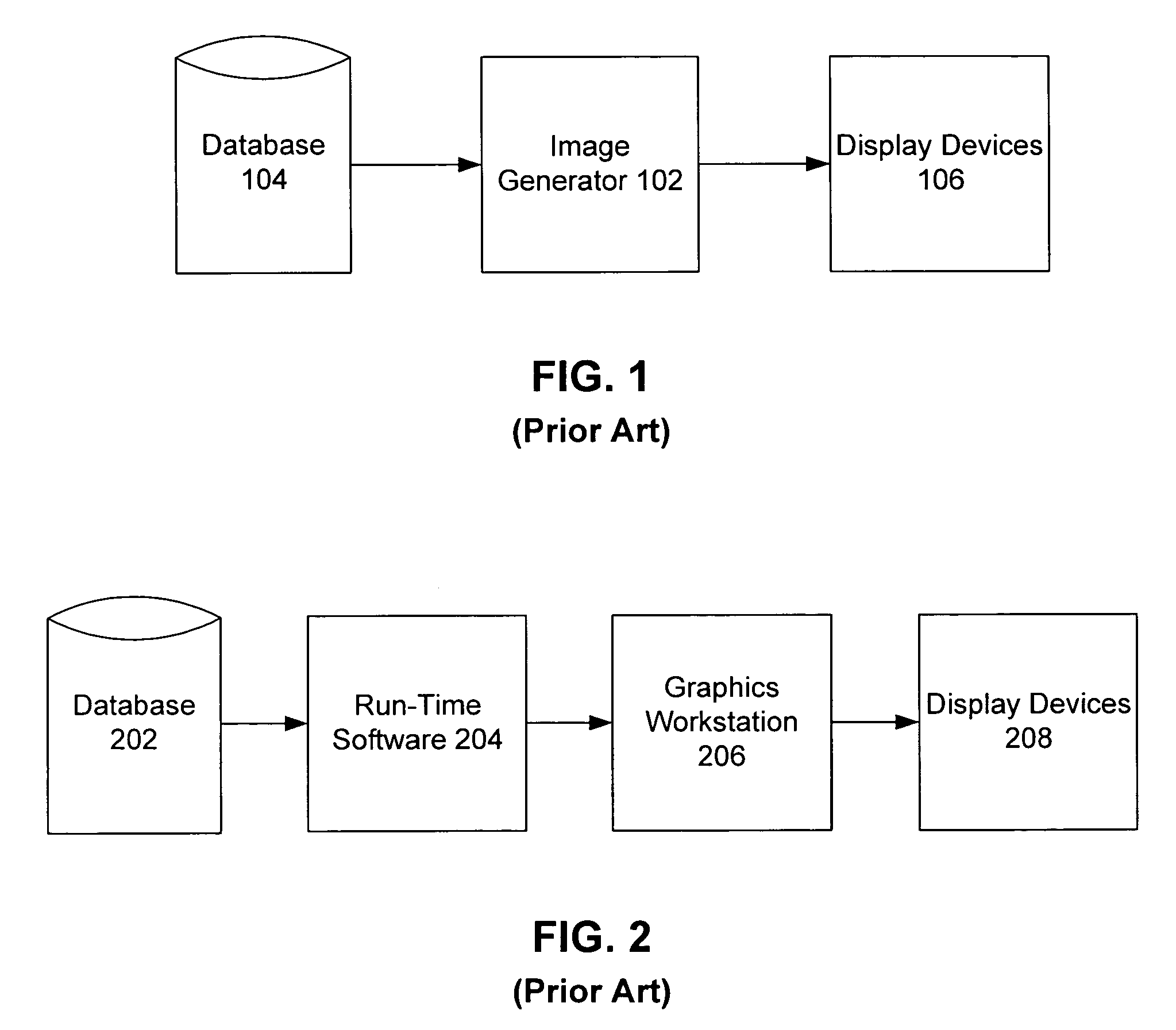
It will likely be harder to build an image generator from these components than from workstations, just as some integrators have found powerful general-purpose workstations more difficult to master than classic dedicated image generators before the advent of the vendor-tuned IRIS Performer API.
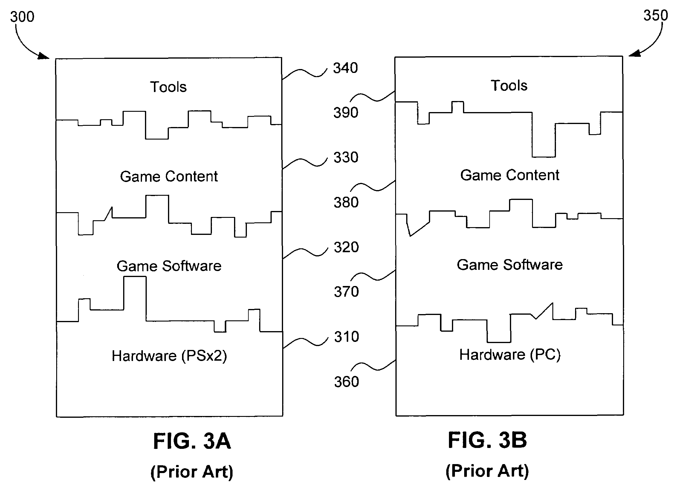
These low-level approaches have an inherent weakness, as evidenced by portable 3D graphics benchmark suites.
Low-level extension mechanisms restrain hardware vendors from optimizing portable applications, for instance by making it impossible to transparently insert multi-processing.
They also tend to stifle innovation by requiring implementation of high-level designs using the specific approach sanctioned by the low-level API developer.
It is even difficult for hardware vendors to add new features using OpenGL's respected extension mechanism, and after having done so, application developers must be enticed to rewrite and re-release their products to incorporate these system-dependent extensions.

Method used


Image

  • System and method for leveraging independent innovation in entertainment content and graphics hardware
  • System and method for leveraging independent innovation in entertainment content and graphics hardware
  • System and method for leveraging independent innovation in entertainment content and graphics hardware

Examples


examples

[0345]This connection wires the block's Left input to the X input of internal block A:

[0346](Connection (From ‘Left) (To ‘A ‘X))

This connection wires the R output internal block A to the input of internal connector B:

[0347](Connection (From ‘A ‘R) (To ‘B))

This connection wires the RGB output of internal block C to the block's Color output:

[0348](Connection (From ‘C ‘RGB) (To ‘Color))

This connection exist within an extension. It wires the Sum output of the extension's internal block D to the basis block's connector C:

[0349](Connection (From ‘D ‘Sum) (To ((Name ‘C)(Basis))))

[0350]Series Connections

[0351]A series connection is a special type of connection that is used in conjunction with a connector.

[0352]To perform a computation on the data that flows through a connector, the computation can be specified using a series property. The computation is inserted into the flow of data at the connector such that the data flowing into the connector is processed, producing new data at the outpu...


PUM


Abstract

A method for supporting development of content independent of a run time platform is provided. A method includes storing processing blocks and storing an application graph that expresses the identity of the stored processing blocks and data connectivity therebetween. The application graph can be traversed by a graphical application platform at run time to execute appropriate blocks. A game development and run time system includes a graphical application platform that enables a game application to run on any of multiple hardware platforms. The graphical application platform has an application real time kernel, a plurality of standard features implemented as executable blocks of logic, and connections between blocks that implement data flow between the blocks. Capabilities of the game application and any of the hardware platforms can be implemented modularly by adding additional corresponding blocks and connections.

Description

[0001]This application claims the benefit of U.S. Provisional Application No. 60 / 223,547, filed Aug. 4, 2000 (incorporated in its entirety herein by reference), and International Application No. PCT / US00 / 32160, filed Nov. 28, 2000 (also incorporated in its entirety herein by reference).BACKGROUND OF THE INVENTION[0002]1. Field of the Invention[0003]The invention relates to computer graphics, and more particularly to development of graphics hardware and software.[0004]2. Related Art[0005]Early Graphics Systems[0006]Early visual systems, such as 1954's DX-50 helicopter trainer from Giravion-Dorand, used optical and mechanical systems and did not make a distinction between the database, the visual system, and the display system. The hardware-centric structure of these systems follows from the ambitious nature of their real-time performance and image quality goals relative to available hardware technology of the day. The birth of image generator technology began with Ivan Sutherland's S...

Claims


Application Information

Patent Timeline
IPC IPC(8): G06F9/44G06F9/46A63F13/00
CPCG06F9/4443G06F8/20A63F2300/203A63F2300/6018A63F2300/66G06F9/451
Inventor TANNER, CHRISTOPHER C.AMAUD, REMI SIMON VINCENTJONES, MICHAEL T.WEBB, RICHARD D.MCCLENDON, BRIAN
Owner ACTIVISION PUBLISHING
Learn More