Blister packaging machine

a packaging machine and blister technology, applied in the direction of packaging goods, pile separation, coin-freed apparatus, etc., can solve the problems of time-consuming and expensive handling, and achieve the effect of simple cleaning and high rotational speed

Inactive Publication Date: 2006-09-12
IWK VERPACKUNGSTECHN
View PDF19 Cites 11 Cited by
  • Summary
  • Abstract
  • Description
  • Claims
  • Application Information

AI Technical Summary

Benefits of technology

[0010]In accordance with the invention, the drive motion of the rotary drive is thereby transferred to the roller brushes in a contact-free manner with the consequence that the wall of the drive gearbox does not need any openings for passage of a drive shaft and the drive gearbox is completely and homogeneously isolated from the brush box to prevent particles from getting from the drive gearbox into the brush box or from the brush box into the drive gearbox.
[0011]Since the magnetic coupling transfers the drive motion from the drive gearbox to the brush box in a contact-free manner, the brush box can be replaced without having to release special mechanical connections between the rotary drive and the roller brushes. In this manner, the brush box can be replaced with another brush box in a rapid and simple manner.
[0016]The bearing wall may be removed along with the second magnets held therein, to provide simple cleaning of the smooth outer side of the drive gearbox during format change.
[0017]In a further development of the invention, the shafts of the roller brushes are each formed as rods which can be removed, whereby individual roller brushes of a brush box can be replaced in a simple advantageous manner by pulling out the shaft disposed in opposite side walls of the brush box, removing the roller brush and subsequently mounting a new roller brush onto the shaft.
[0018]The drive motors can be controlled independently of each other and their rotational speed can be varied. If a new product is supplied to the upper side of the brush box, it takes some time for the product, e.g. tablets, to be distributed over the entire brush box through rotation of the roller brushes. To accelerate distribution of the tablets in the brush box after format change, the direction of rotation of the drive motors may also be reversed, thereby permitting precise transport of tablets within the brush box through corresponding control of the drive motors.
[0021]To prevent excessive formation of dust within the brush box, the brush box may have an associated suction device to vacuum dust.

Problems solved by technology

Such handling is time-consuming and expensive.
Since product dust or product chips are always produced in the region of the brush box, the above-mentioned brush box structure always bears the risk of having these particles penetrate into the coupling and the opening region of the drive shafts, thereby soiling it.

Method used


Image

  • Blister packaging machine
  • Blister packaging machine
  • Blister packaging machine

Examples


Embodiment Construction

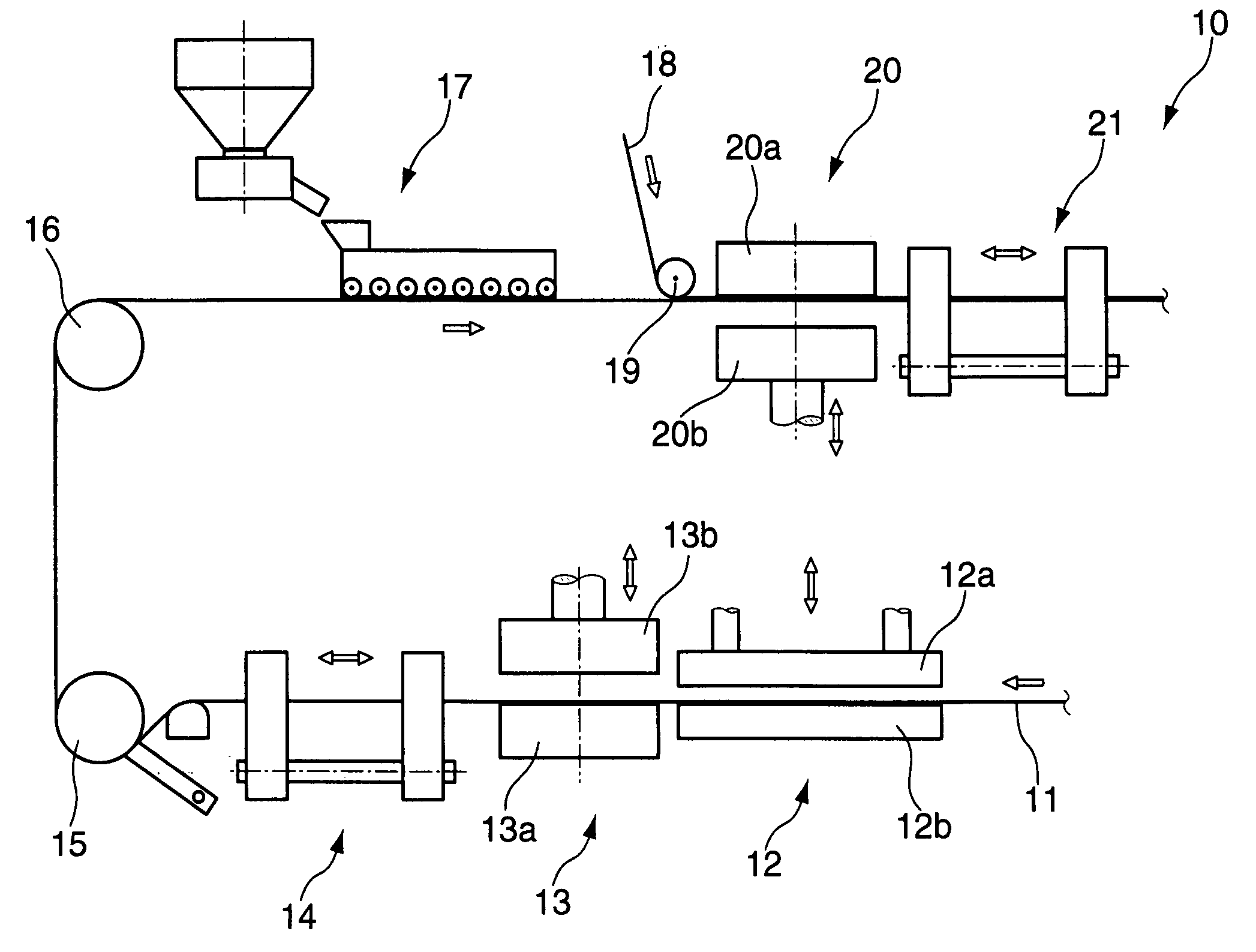
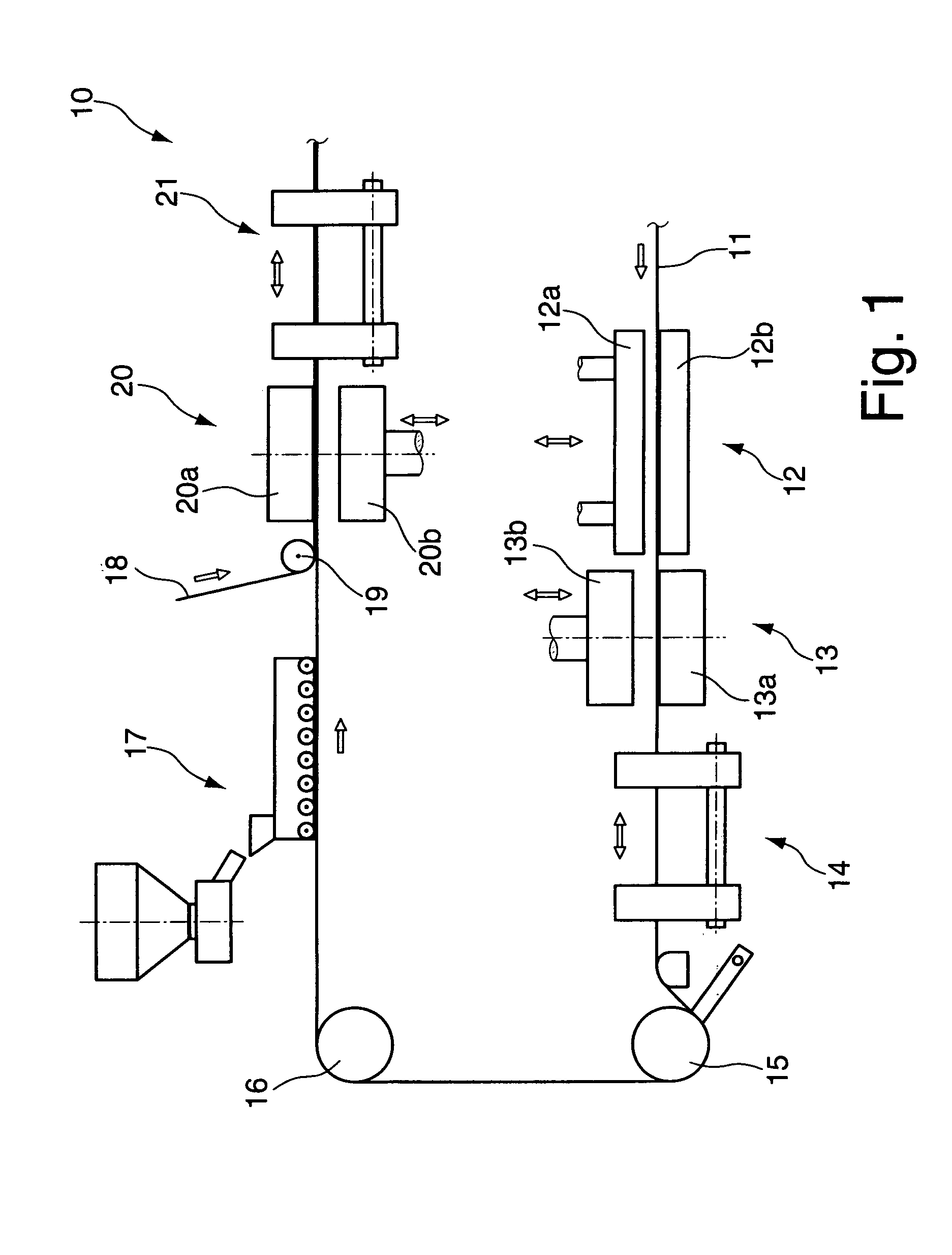
[0028]FIG. 1 shows a schematic view of the essential components of a blister packaging machine 10. A bottom sheet 11 of plastic material is delivered from a supply and is initially guided to a heating station 12 which comprises a lower heating plate 12b and an upper heating plate 12a which can be adjusted relative to the lower heating plate 12b. When the two heating plates 12a and 12b are closed, the bottom sheet 11 received between them is heated.

[0029]A forming station 13 directly borders the heating station 12 and comprises a lower forming plate 13a and an upper forming plate 13b which can be adjusted relative thereto. The two forming plates 13a and 13b, which are shown in an open position, can be closed, wherein the bottom sheet which is received between the closed forming plates 13a and 13b is cooled and simultaneously provided with cup-shaped depressions through supply of pressurized air or through forming dies. The forming station 13 is joined by a transport device 14 for dra...


PUM

PropertyMeasurementUnit
magneticaaaaaaaaaa
magnetic couplingaaaaaaaaaa
sizeaaaaaaaaaa

Abstract

A blister packaging machine comprises a forming station in which a plurality of cup-shaped depressions can be formed into a bottom sheet, a filing station, in which a product can be filled into the cup-shaped depressions, and a downstream sealing station, in which a cover sheet can be sealed onto the bottom sheet. The filling station comprises a brush box disposed above the bottom sheet, in which several rotatably driven roller brushes are disposed parallel to each other. The roller brushes are connected to a rotary drive which is received in a drive gearbox disposed next to the brush box. A magnetic coupling is thereby provided for transmitting a drive motion of the rotary drive to the roller brushes through a wall of the drive gearbox.

Description

[0001]This application is the national stage of PCT / EP2004 / 000380 filed on Jan. 20, 2004 and also claims Paris Convention priority of DE 103 02 725.4 filed Jan. 23, 2003.BACKGROUND OF THE INVENTION[0002]The invention concerns a blister packaging machine comprising a forming station, in which a plurality of cup-shaped depressions can be formed into a bottom sheet, a filling station, in which a product can be filled into the cup-shaped depressions, and a downstream sealing station in which a cover sheet can be sealed onto the bottom sheet, wherein the filling station comprises a brush box which is disposed above the bottom sheet and which contains several rotary driven roller brushes disposed parallel and next to each other, the roller brushes being connected to a rotary drive which is accommodated in a drive gearbox disposed next to the brush box.[0003]A blister packaging machine of conventional structure comprises a forming station, in which a plurality of cup-shaped depressions are...

Claims


Application Information

Patent Timeline
Patent Type & Authority Patents(United States)
IPC IPC(8): B65B47/00B65B9/04
CPCB65B9/04
Inventor HAHNEL, BERND
Owner IWK VERPACKUNGSTECHN
Why Eureka
Try Eureka