
Damping arrangement for reducing combustion-chamber pulsation in a gas turbine system

a gas turbine and pulsation technology, which is applied in the direction of mechanical equipment, machines/engines, lighting and heating apparatus, etc., to achieve the effect of simplify avoiding further complicating the casting process, and improving the damping degree of the arrangemen

Inactive Publication Date: 2006-09-12
ANSALDO ENERGIA SWITZERLAND AG
View PDF39 Cites 46 Cited by
  • Summary
  • Abstract
  • Description
  • Claims
  • Application Information

AI Technical Summary

Benefits of technology

[0013]Accordingly, one object of the invention is to provide novel damping measures by means of which effective damping of combustion-chamber pulsations forming within a combustion chamber of the type described above is possible without, at the same time, permanently prejudicing those properties of the combustion chamber that have been optimized for combustion. It is especially the object to find damping measures for which the design requirements entail as small a construction as possible so that they can be integrated in a space-saving manner into combustion-chamber systems of the abovementioned type. In particular, this should leave open the option of integrating the combustion chamber into systems in which space is only limited.
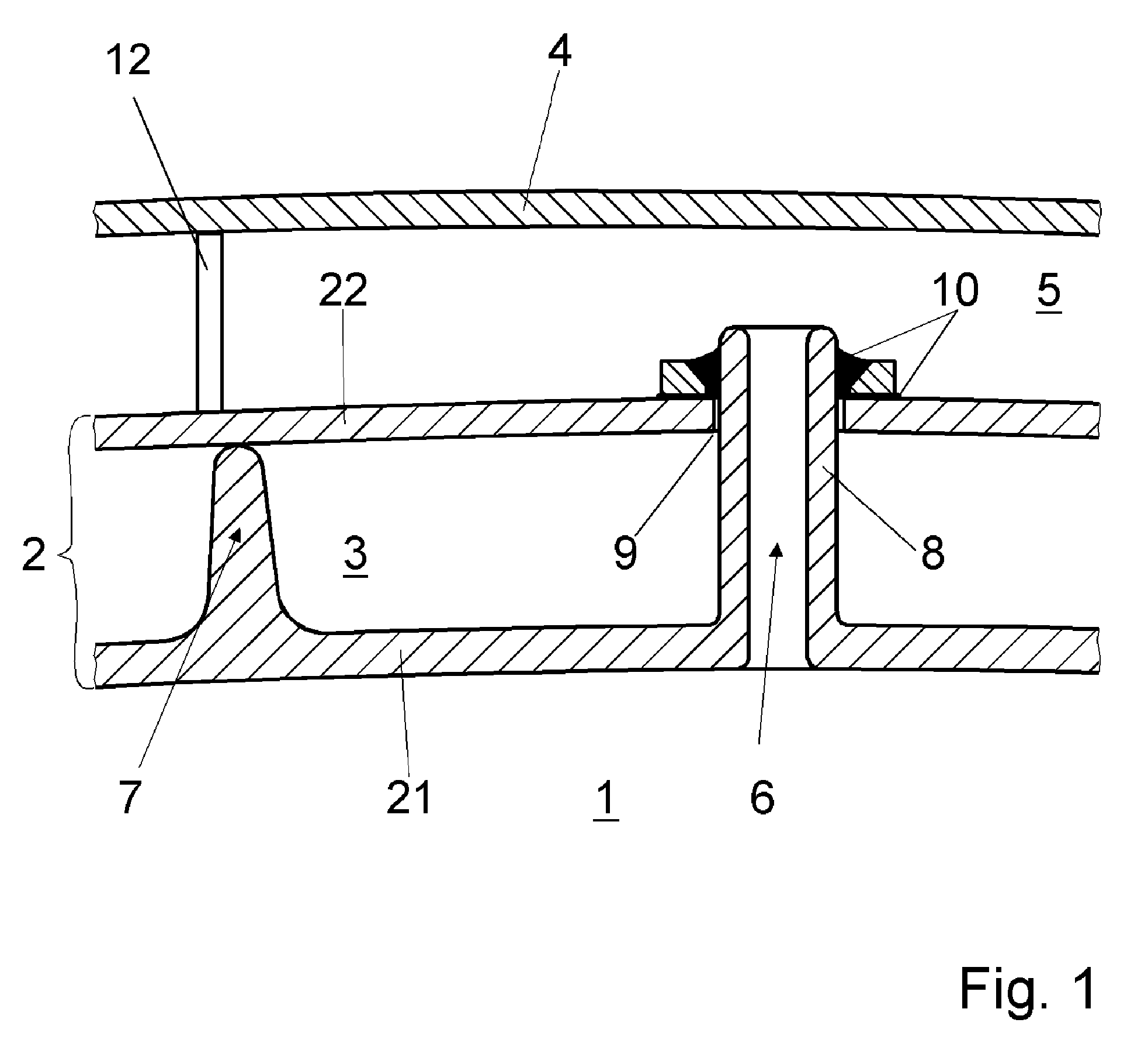
[0016]To couple the absorber volume delimited by the third wall-surface part acoustically to the interior of the combustion chamber, the connecting line designed as a connecting tube projects locally through the intermediate space of the combustion chamber of double-walled design, through which intermediate space there is a flow of cooling air, and is simultaneously cooled in an effective manner by the flow of cooling air around it. This has the advantage that there does not have to be a separate flow of air through the connecting tube for cooling purposes. It is also possible to prevent heating or overheating of the absorber volume on the part of the combustion chamber through the connecting tube, particularly because, as mentioned above, it undergoes effective cooling. If the cooling effect on the connecting tube of the cooling air flowing around the connecting tube is nevertheless not sufficient, a selective flow of cooling air through the connecting tube can supply the cooling effect that is lacking. This supplementary cooling effect can be accomplished either with the cooling air from the intermediate space and / or from outside the combustion chamber, e.g. from the plenum through an opening within the third wall-surface part. A stream of cooling air of this kind, directed through the connecting tube, should have a flow velocity of less than 10 m / s, however.
[0026]It is also advantageous in this context to make the third wall-surface part delimiting the absorber volume elastic in order to further improve the degree of damping of the arrangement.
[0027]The double-walled combustion-chamber wall is composed in a manner known per se of two wall-surface parts, which can both be produced by way of a casting process. For the exact mutual spacing of the two wall-surface parts, the inner wall-surface part provides so-called longitudinal ribs as spacing elements and holding ribs as fixing webs, by means of which the two wall-surface parts can be connected firmly to one another while maintaining an exact spacing. To avoid further complicating the casting process and indeed to simplify it, the connecting lines designed as connecting tubes are provided along a holding rib, which is provided in any case, enabling the connecting tube and the holding rib to be produced as a one-piece constructional unit together with the inner wall-surface part in a single casting step. This measure furthermore makes the production, by casting, of the inner wall-surface part with an exactly specifiable wall-surface thickness considerably easier, thereby making it possible to achieve large-area wall-surface parts with specifiable constant dimensioning without deviations in thickness.

Problems solved by technology

If the cooling effect on the connecting tube of the cooling air flowing around the connecting tube is nevertheless not sufficient, a selective flow of cooling air through the connecting tube can supply the cooling effect that is lacking.

Method used


Image

  • Damping arrangement for reducing combustion-chamber pulsation in a gas turbine system
  • Damping arrangement for reducing combustion-chamber pulsation in a gas turbine system
  • Damping arrangement for reducing combustion-chamber pulsation in a gas turbine system

Examples


Embodiment Construction

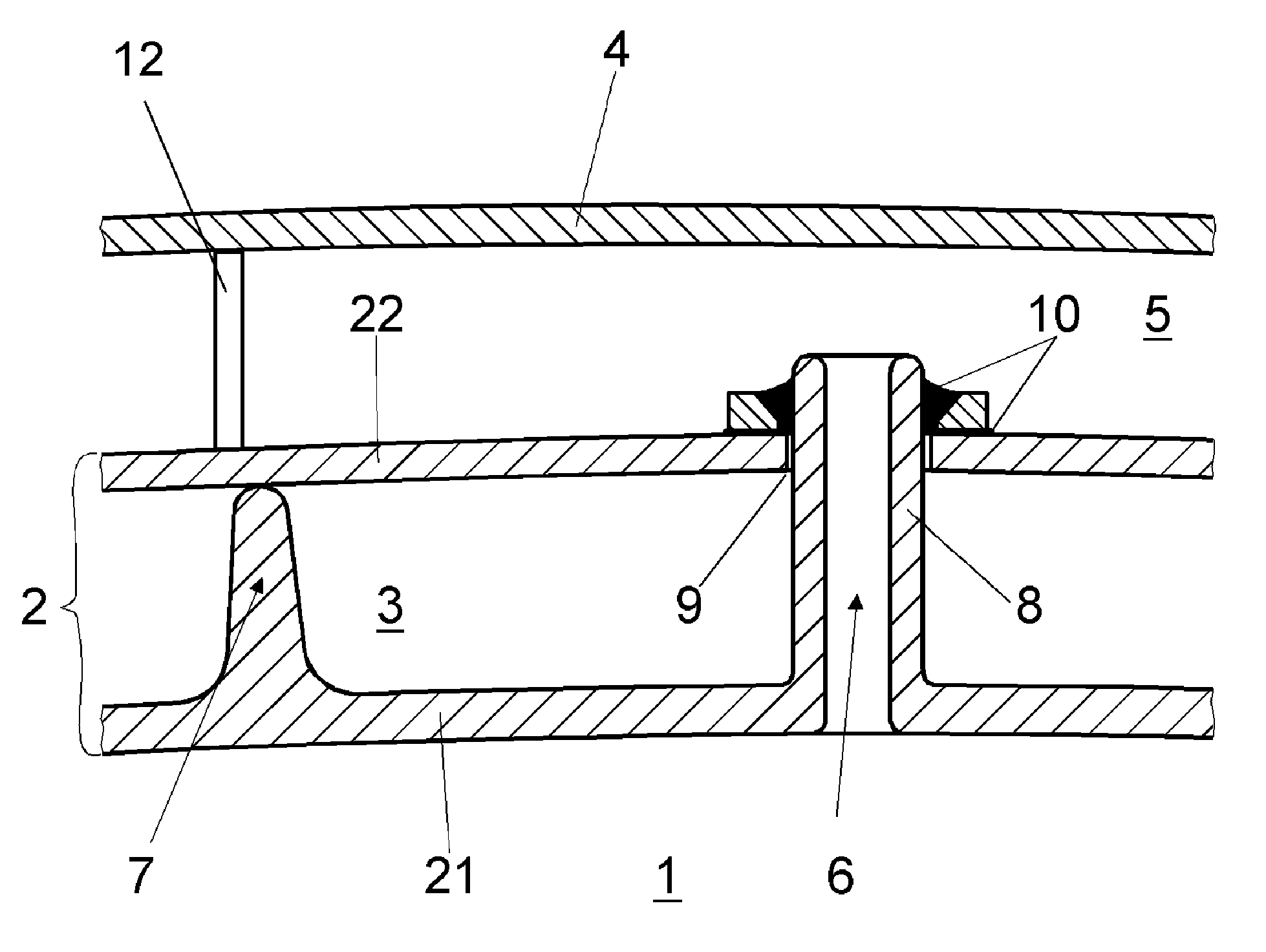
[0033]Referring now to the drawings, wherein like reference numerals designate identical or corresponding parts throughout the several wiews, FIG. 1 shows a cross-sectional representation of a damping arrangement for reducing resonant vibrations in a combustion chamber 1 surrounded by a combustion-chamber wall 2, which is of double-walled design and, with an outer wall-surface part 22 and an inner wall-surface part 21, gastightly surrounds an intermediate space 3, into which cooling air can be fed for purposes of convective cooling of the combustion-chamber wall 2, in particular of the inner wall-surface part 21.

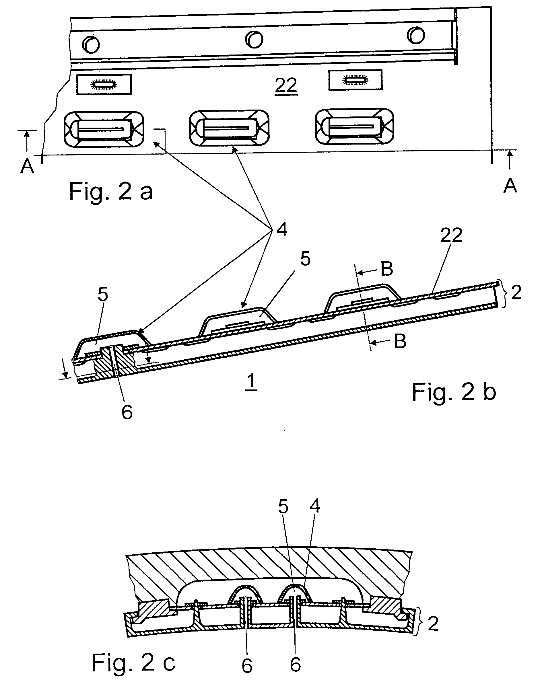
[0034]Provided on the opposite side of the outer wall-surface part 22 from the combustion chamber 1 is a third wall-surface part 4, which, with the outer wall-surface part 22, encloses a gastight volume, referred to as the resonance or absorber volume 5. Via a connecting line 6 in the form of a connecting tube, the absorber volume 5 is connected directly to the combustion ch...


PUM


Abstract

A description is given of a damping arrangement for reducing resonant vibrations in a combustion chamber (1), with a combustion-chamber wall (2), which is of double-walled design and, with an outer wall-surface part (22) and an inner wall-surface part (21) facing the combustion chamber (1), gastightly encloses an intermediate space (3), into which cooling air can be fed for purposes of convective cooling of the combustion-chamber wall (2).The invention is distinguished by the fact that at least one third wall-surface part (4) is provided, which, with the outer wall-surface part (22), encloses a gastight volume (5), and that the gastight volume (5) is connected gastightly to the combustion chamber (1) by at least one connecting line (6).

Description

[0001]This is a U.S. national stage patent application filed under 35 U.S.C. § 371 of International application number PCT / IB02 / 03492, filed 28 Aug. 2002, which claims priority to Swiss application number 2001 1663 / 01, filed 7 Sep. 2001, the entireties of both of which are incorporated by reference herein.BACKGROUND OF THE INVENTION[0002]1. Field of the Invention[0003]The invention relates to a damping arrangement for reducing resonant vibrations in a combustion chamber, with a combustion-chamber wall which is of double-walled design, and, with an outer wall-surface part and an inner wall-surface part facing the combustion chamber, gastightly encloses an intermediate space, into which cooling air can be fed for purposes of convective cooling of the combustion-chamber wall.[0004]2. Discussion of Background[0005]A combustion chamber with a combustion-chamber wall of double-walled design mentioned above emerges from EP 0 669 500 B1. There is a flow of compressed combustion feed air for...

Claims


Application Information

Patent Timeline
IPC IPC(8): F02C7/24F23M20/00F23R3/06F23R3/00F23R3/22
CPCF23R3/002F23M20/005F23R2900/00014
Inventor BENZ, URSHELLAT, JAANJOOS, FRANZ
Owner ANSALDO ENERGIA SWITZERLAND AG
Learn More