Hydraulic control circuit for a hydraulic lifting cylinder

a hydraulic cylinder and control circuit technology, applied in the direction of servomotors, lifting devices, servomotor components, etc., can solve the problems of high degree of control inertia, boom or tool being lowered uncontrollable, system without load-holding valves, etc., to achieve the effect of increasing safety risks and without costly configuration

Active Publication Date: 2006-09-12
DEERE & CO
View PDF11 Cites 16 Cited by
  • Summary
  • Abstract
  • Description
  • Claims
  • Application Information

AI Technical Summary

Benefits of technology

[0007]According to the invention, a control system or circuit of the type noted initially is equipped with a valve arrangement that controls the flow rate as a function of the flow in the first hydraulic line. A valve arrangement that controls as a function of the flow rate has the advantage that the flow rate can be controlled independently of the pressure in the hydraulic line so that only a certain flow amount reaches through the hydraulic line with a low as well as a high hydraulic load and thereby a safety function is offered. If, for example, while the first chamber of the hydraulic cylinder is loaded with pressure, the valve arrangement is brought into the floating position in which the on-off valve is switched into a through-flow position by a switching signal, then the valve arrangement controlling as a function of the flow rate provides the assurance that the flow rate can change only within certain limits or does not exceed a certain value independently of the magnitude of the pressure.
[0022]There is a particular advantage in the fact that through the configuration of the invention a floating position for a telescopic loader is assured while maintaining a load-holding valve arrangement (pipe break safety device) that is relevant to safety requirements. Furthermore, an interface can be realized, without costly configurations, so that the lifting devices already existing on a telescopic loader or the main valve need not be changed. Thereby the number of valve blocks can be kept to a minimum and the possibility of a retrofit or an improvement to an existing product is assured with the use of the same lifting cylinder with various differing options. Beyond that other variations are also conceivable that combine a floating position function, for example, with a hydraulic spring function, so that starting with a basic version with a load-holding valve arrangement a modular expansion with a floating position function and, beyond that, a modular expansion of the spring function is possible.

Problems solved by technology

Such control systems do not contain any load-holding valves that prevent or sharply slow an unintended lowering of the boom or loader arm for reasons of safety when a leakage is encountered in the connection between the cylinder and control valve.
Here the disadvantage is that the throttling is performed over a control arrangement supplied by a pump that is costly in its configuration as a control valve and results in a high degree of control inertia and at high loads unintended and uncontrolled pivoting movements result upon shifting to a floating position despite the throttling.
Furthermore, the control system does not contain a load-holding valve to secure the hydraulic operation of the consumer.
The disadvantage then is that upon switching under load, the boom or the tool would be lowered uncontrolled.
The disadvantage is that upon switching into the floating position under load, the constant cross section of the throttle, designed for the operation, cannot control the lowering of the pressure side.
Furthermore such a one-way restrictor does not represent a load-holding valve, which could prevent an uncontrolled lowering of the load in its operating position.

Method used


Image

  • Hydraulic control circuit for a hydraulic lifting cylinder
  • Hydraulic control circuit for a hydraulic lifting cylinder
  • Hydraulic control circuit for a hydraulic lifting cylinder

Examples


Embodiment Construction

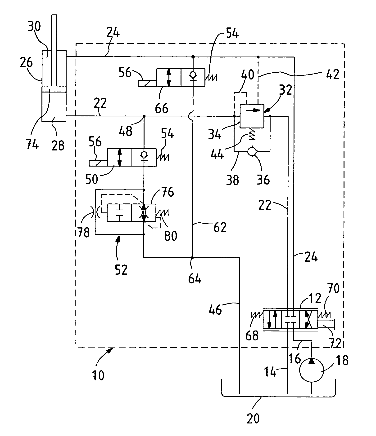
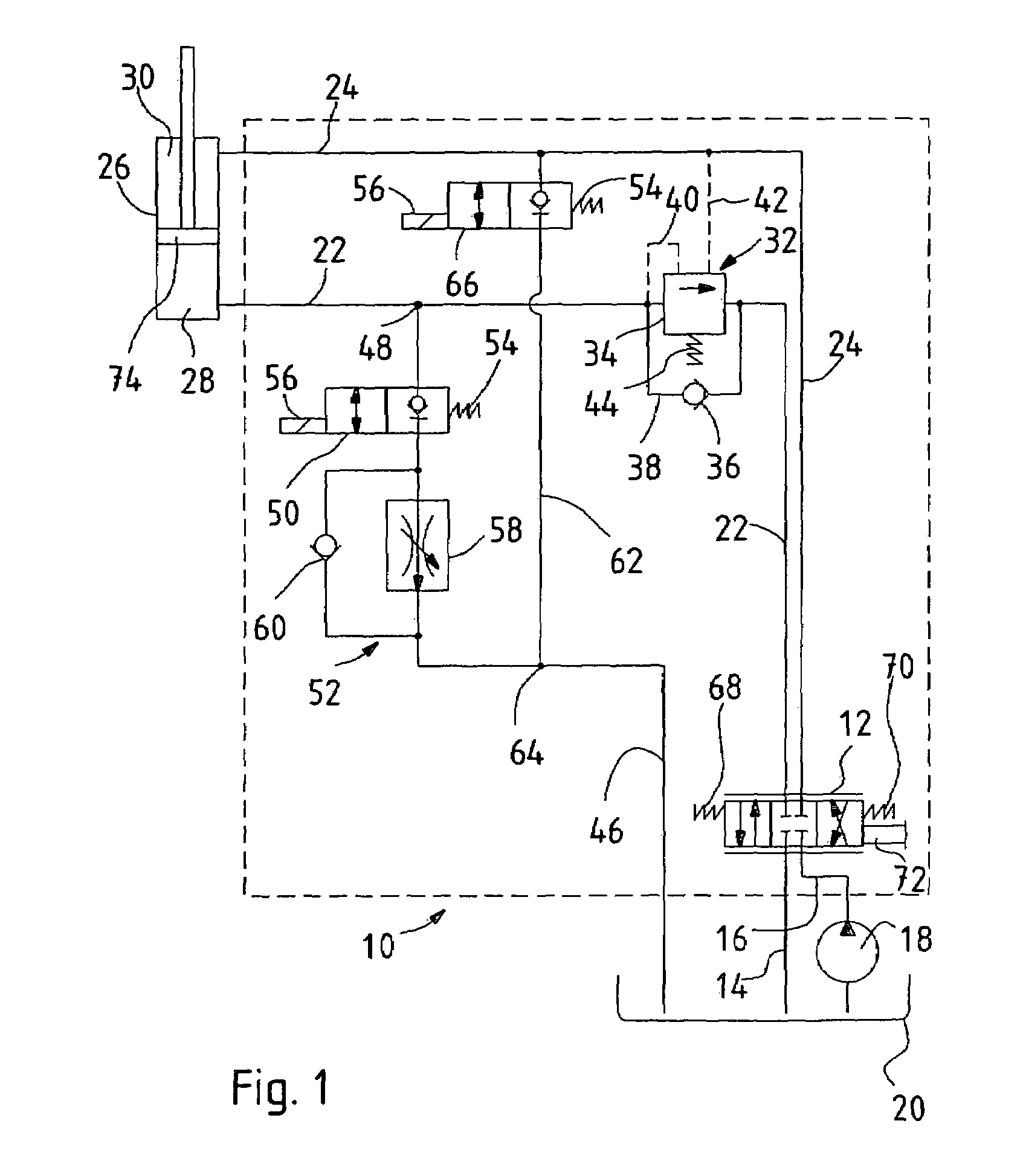
[0027]The circuit diagram shown in FIG. 1 shows an embodiment of a hydraulic control system or circuit 10 for achieving a floating position in a hydraulic consumer. The control system 10 contains a control valve 12 that can be switched, for example, a slide valve that is connected by hydraulic lines 14 and 16, respectively to a pump 18 and a hydraulic reservoir 20 where the control valve 12 can be switched into three operating positions, namely, lifting, neutral and lowering. The switching of the control valve 12 is preferably performed manually, but can also be performed electrically, hydraulically or pneumatically.

[0028]The control valve 12 is connected over first and second supply lines 22 and 24, respectively, to a hydraulic cylinder 26, where the first supply line 22 leads to a first chamber 28 of the hydraulic cylinder 26 and the second supply line 24 leads to a second chamber 30 of the hydraulic cylinder 26. The first chamber 28 of the hydraulic cylinder 26 represents the pis...


PUM


Abstract

A hydraulic control circuit for a hydraulic cylinder is described for the raising and lowering of a boom on a telescopic loader. First and second chambers of the hydraulic cylinder are connected to a control valve over first and second supply lines and are selectively connected to either a hydraulic pressure source or to a hydraulic reservoir. The circuit includes on-off valves for controlling the flow through a first hydraulic line extending between the first chamber of the cylinder and the hydraulic reservoir, and through a second hydraulic line extending between the second chamber and the hydraulic reservoir in such a way that a floating position can be provided. Furthermore, a load-holding valve arrangement is provided in the first supply line at a location between the control valve and the first chamber of the cylinder. To provide assurance against uncontrolled lowering of the boom during switching to the floating position under load, a valve arrangement is provided that controls the flow rate as a function of the flow rate.

Description

FIELD OF THE INVENTION[0001]The invention concerns a hydraulic control circuit for a hydraulic cylinder with a control valve that selectively connects at least a first chamber of the hydraulic cylinder over a first supply line with a hydraulic pressure source or a hydraulic reservoir. Furthermore the valve arrangement includes a first on-off valve that controls the flow through the first hydraulic line extending between the first chamber and the hydraulic reservoir, and which opens on the basis of a switch signal, whereby a floating position can be provided.BACKGROUND OF THE INVENTION[0002]Hydraulic float control systems, in which floating positions have been implemented that permit a free movement of a hydraulic consumer, are known in the state of the art. Here, both connecting sides of the hydraulic consumer are connected to each other as well as at low pressure or without pressure to a hydraulic container or reservoir. Float control systems of this type are applied to constructio...

Claims


Application Information

Patent Timeline
Patent Type & Authority Patents(United States)
IPC IPC(8): F15B11/044B66F9/065B66F9/22F15B11/00F15B11/024
CPCB66F9/0655F15B11/003F15B11/024B66F9/22F15B2211/7741F15B2211/20538F15B2211/30525F15B2211/3111F15B2211/3144F15B2211/31576F15B2211/324F15B2211/327F15B2211/40515F15B2211/40584F15B2211/41581F15B2211/46F15B2211/473F15B2211/50581F15B2211/5153F15B2211/5154F15B2211/528F15B2211/7053
Inventor BITTER, MARCUSPRICE, DAVIDSCHLEMMER, STEFFENONNEN, MARLIN
Owner DEERE & CO
Why Eureka
Try Eureka