
Contractile unit having a position sensor means

a position sensor and contractile unit technology, applied in the field of contractile units, can solve the problems of extreme high setting force, but for the most part unsuitable or badly suited, and achieve the effect of satisfying the focussing or directionality of the emitted microwave beam

Inactive Publication Date: 2006-09-12
FESTO AG & CO KG
View PDF21 Cites 8 Cited by
  • Summary
  • Abstract
  • Description
  • Claims
  • Application Information

AI Technical Summary

Benefits of technology

[0005]One object of the present invention is accordingly to create a position sensor means which is highly suitable for such contractile units and is able to be produced simply and at a low cost while ensuring high accuracy.
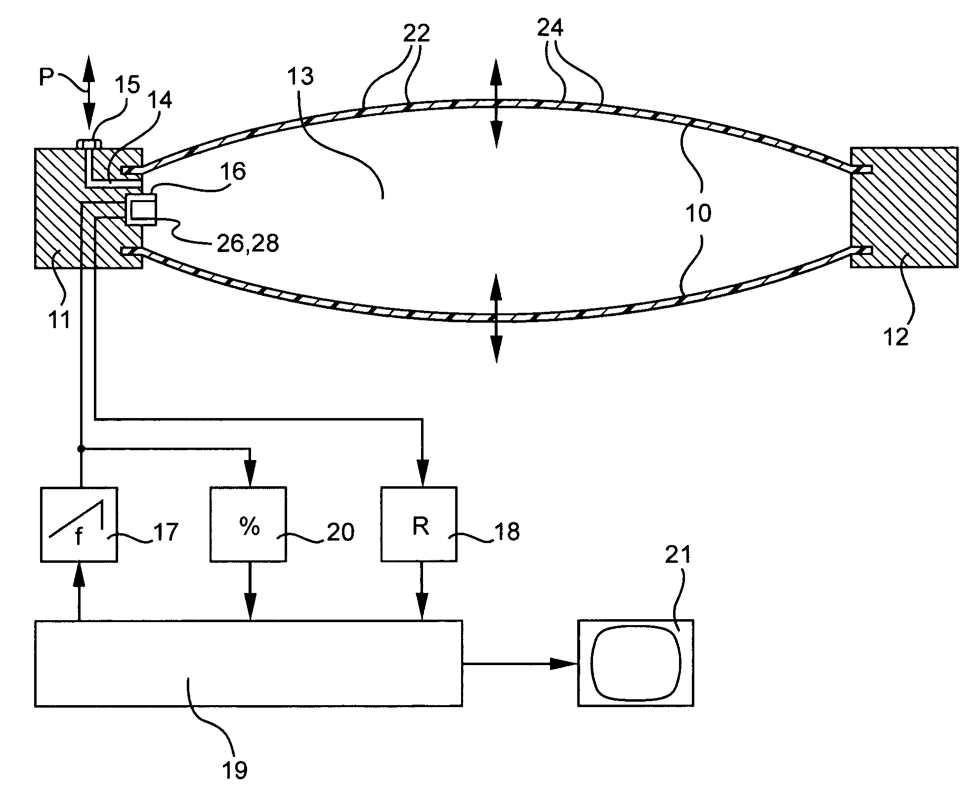
[0007]The advantages of the design in accordance with the invention are more particularly that such a microwave generator, which is already commercially available at an extremely low price in a miniaturized form, may be very easily mounted on the inner side of one of the head pieces or may be integrated in one of the head pieces. Owing to the arrangement in the interior space of the contractile unit without external measuring elements the compactness of the contractile unit is not reduced and mechanical damage or interference is excluded as regards the position sensor means to a substantial extent. One of the principal advantages of such contractile units, namely the complete sealing and accordingly the small amount of working fluid needed, is not impaired by the position sensor means. The measurement of the distance between the head pieces and accordingly the detected position may be performed with great accuracy.
[0009]The microwave generator is advantageously also designed as a microwave receiver so that the reflected microwaves may be detected using the same compact component. This results in a simplification of the electrical connections of the position sensor means.
[0013]According to a convenient design, the microwave generator is designed as a coupled probe transmitting and receiving microwaves. As an alternative to this, the microwave generator may also be designed as a cavity resonator with a resonance space open toward the oppositely placed head piece of the contractile unit. This provides a satisfactory focussing or directionality of the emitted microwave beam.

Problems solved by technology

Extremely high setting forces may be produced.
In the case of contractile units of the above noted type the same are however for the most part unsuitable or badly suited.

Method used


Image

  • Contractile unit having a position sensor means
  • Contractile unit having a position sensor means

Examples


Embodiment Construction

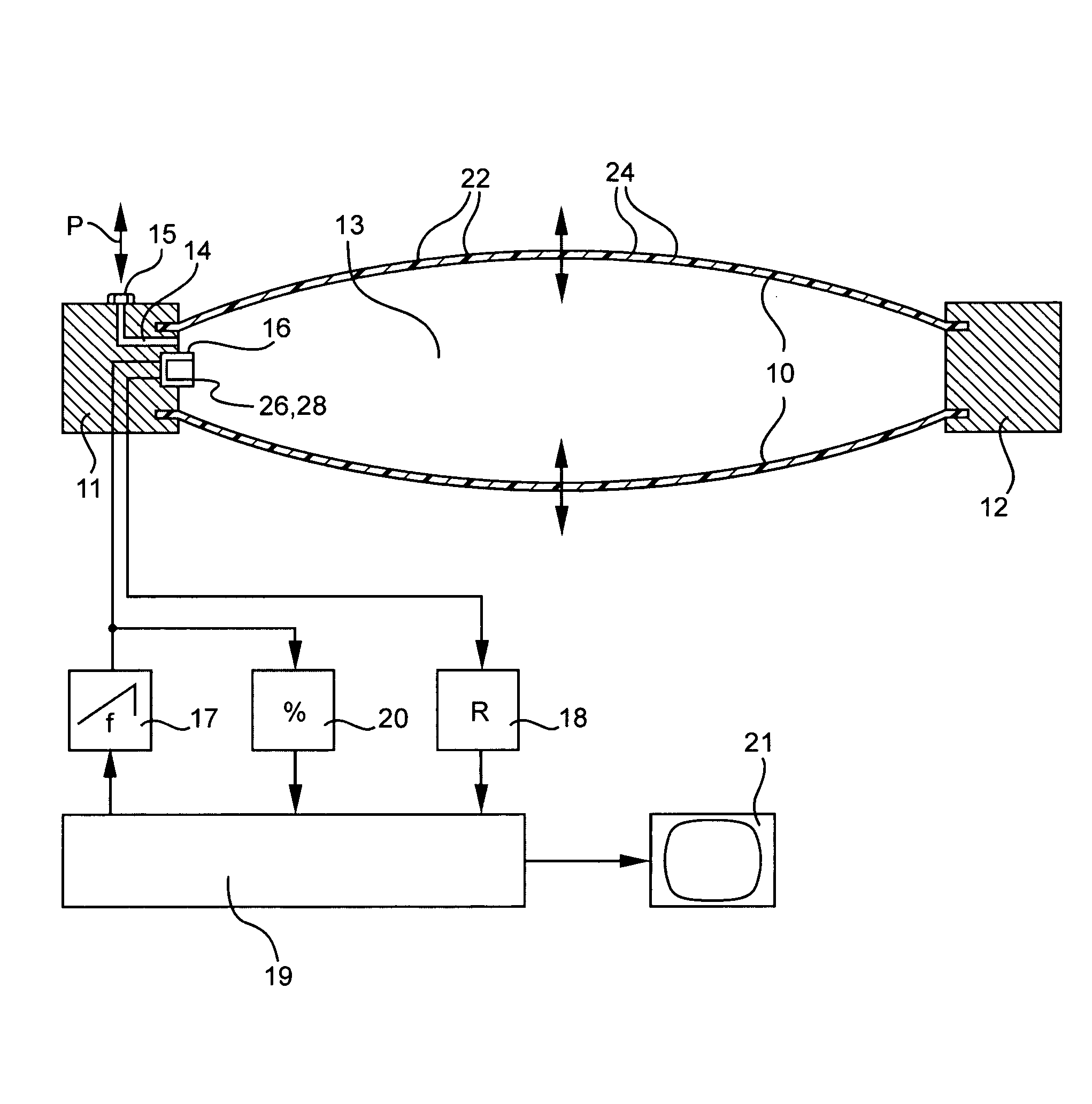
[0015]The contractile element is only diagrammatically represented in the single figure for simplification. A more detailed representation is to be found for example in the initially mentioned German patent publication (utility model) 29,906,626. A contractile hose 10 of an elastic rubber or plastic material is sealed off both ends by head pieces 11 and 12. In the wall of the contractile hose 10, there is a conventional flexible strand structure which is not illustrated to simplify the drawing and which in the present case may consist of metallic strand structures 22 in order to let the contractile unit function as a microwave wave guide. The wall can also comprise other metallic conductive particles 24. The connection of the contractile hose 10 with the two head pieces 11 and 12 is such that the contractile hose 10 provided with the strand structure 22 is able to transmit tension forces to the respective head piece 11 and 12. The attachment may for example be as part of a clamping ...


PUM


Abstract

A contractile unit comprising a contractile hose extending between two spaced head pieces and adapted to perform a longitudinal contraction on being subjected to internal pressure, and a position sensor means responsive to the distance between the head pieces. The position sensor means possesses a microwave generator arranged on one of the head pieces and adapted to emit microwaves into the interior space of the contractile unit, an evaluating means being provided responsive to the distance between the head pieces using transit time measurement, phase comparison of the emitted and reflected wave or using determination of the resonant frequency.

Description

[0001]This application is a National Phase application of International Application No. PCT / EP03 / 04859 filed May 9, 2003, which claims priority based on German patent application No. 102 25 246.7 filed on Jun. 7, 2002, which are incorporated herein by reference.FIELD OF THE INVENTION[0002]The invention relates to a contractile unit comprising a contractile hose extending between two spaced apart head pieces and adapted to perform a longitudinal contraction.BACKGROUND OF THE INVENTION[0003]Such contractile units are for example disclosed in the assignee's brochure “Fluidic Muscle”, the European patent publication 0 161 750 B1, the German patent publication (utility model) 29,906,626, the German patent publication (utility model) 29,908,008 or the German patent publication (utility model) 20,112,633 and are suitable for highly exact positioning while having a simple and low-wear structure involving relatively low costs. Extremely high setting forces may be produced.[0004]For precise p...

Claims


Application Information

Patent Timeline
IPC IPC(8): F01B31/12F15B15/10F15B15/28G01S13/32
CPCF15B15/2869F15B15/103
Inventor REININGER, THOMAS
Owner FESTO AG & CO KG
Learn More