Watercraft stabilizing device

a technology for stabilizing devices and watercraft, which is applied in the direction of special-purpose vessels, vessel construction, and vessel movement reduction by foils, etc. it can solve the problems of either solution not being effective, vehicle susceptible to the effects, and vehicle to drift either away, so as to achieve the effect of adding lateral stability to the boat and being easy to install and remove from the boa

Inactive Publication Date: 2006-09-12
WIDLACKI DON FELIX
View PDF2 Cites 0 Cited by
  • Summary
  • Abstract
  • Description
  • Claims
  • Application Information

AI Technical Summary

Benefits of technology

[0007]The present invention provides a pivoting boat stabilizing device comprising a generally blade-shaped stabilizer with needed extra and additional downward angles for more surface area where needed most to totally control and stop drift and any motion and is attached to a boat that projects into the water in such a manner as to counter any movement of the boat at an angle to the longitudinal axis, such movements are the result of such things as wind, water currents, and other forces acting upon the boat from in or on the boat itself. This pivoting stabilizer with its extra downward angles provides resistance at an angle to the force countering the resultant unwanted motion of the boat. When the boat is stationary, the present invention operates to maintain the stationary position of the boat. When the boat is in motion, the device operates to keep the boat from drifting or moving off or away from any desired heading. This invention is designed in such a manner that it provides that complete additional lateral stability to a boat, while also being designed such that it a) is easy to install and remove from the boat when it is either in or out of the water; b) is light and durable; c) may withstand impacts on submerged objects without being damaged or breaking by pivoting relative to a trough or slot in the holder to allow the invention to pivot and either move freely away or causing it to distribute the impact throughout the boat in the event that the devices encounters the submerged object in either a forward, backward or sideways impact manner; d)is free to move in a vertical direction above and over submerged objects, and e) may be removed and used in an emergency by the operator or other persons as a spare paddle.
[0008]The present invention can be either build into the boat as a permanent part thereof, or as a system that is installed after the boat has been constructed. There are advantages to both, but the post-construction installation reduces cost and is easy to install, position for optimal stabilization, and remove. Further, an embodiment of the present invention allows for its quick removal to use as a spare paddle in the vent of an emergency.

Problems solved by technology

When stationary in or on the surface of a body of water, most water-borne vehicles provide large surface areas along the longitudinal axis that makes the vehicle susceptible to the effects of forces such as water currents and wind, among other things.
Such forces can cause the vehicle to drift either away from the desired stationary position or off of the desired course heading.
Either solution is not an effective answer to the problem for several reasons.
First, it requires the constant vigilance and attention of the boater, often at a time when they are focusing on the task at hand, such as fishing.
It distracts them, and may require sacrificing a fish catch merely to adjust the boat's position.
Secondly, it wastes either gas in an outboard engine or battery power in a trolling motor.
Third, it creates noise and water turbulence that could negatively impact fishing results.
Finally, it is not an efficient or effective way to counter forces that are directed at an angle to the longitudinal axis of the boat.
The need for such constant course corrections wastes time and fuel.

Method used


Image

  • Watercraft stabilizing device
  • Watercraft stabilizing device
  • Watercraft stabilizing device

Examples


Embodiment Construction

[0028]The following is the preferred embodiment or best mode for carrying out the invention. It should be noted that this invention is not limited by the discussion of the preferred embodiment and should only be defined by the appended claims.

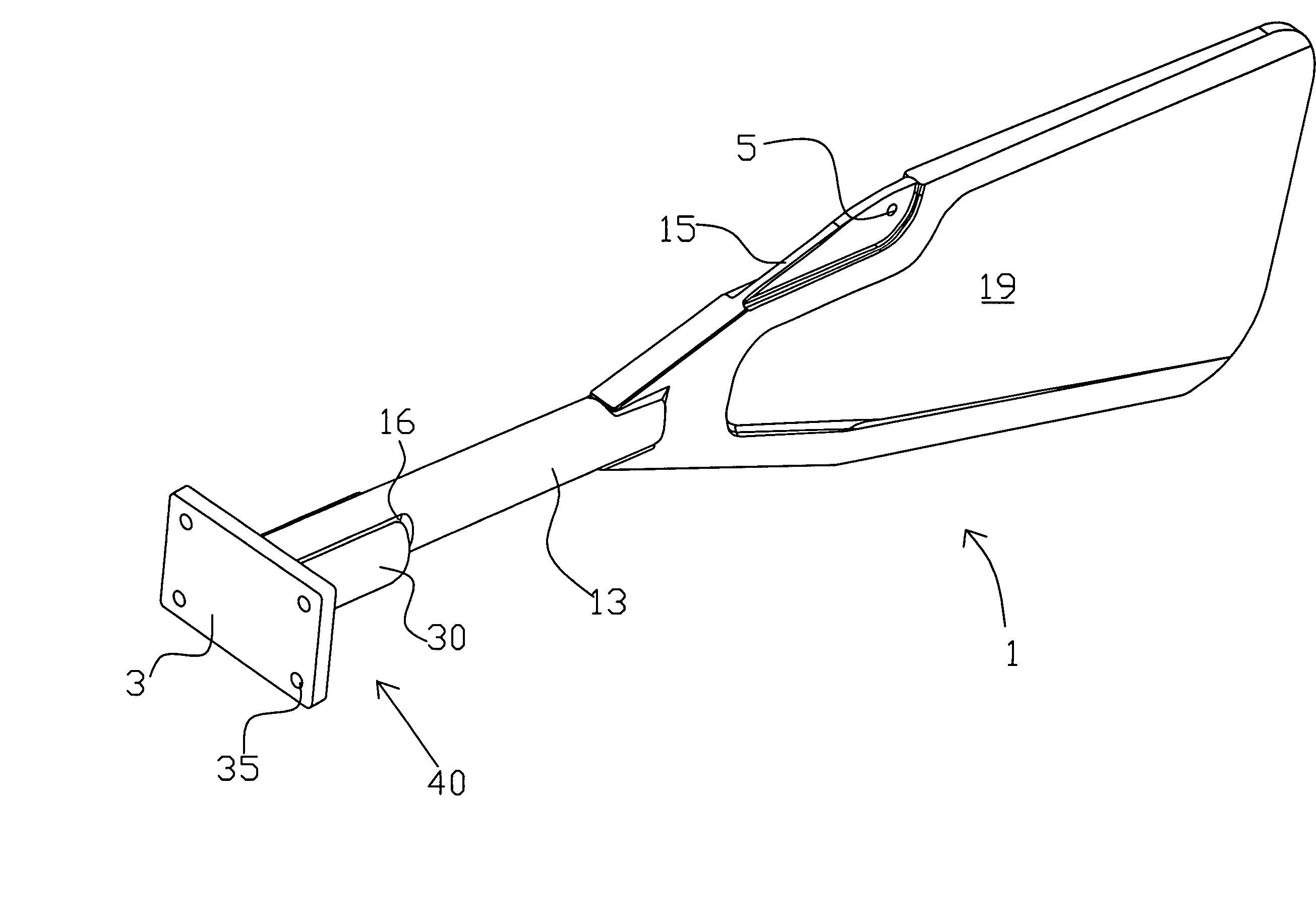
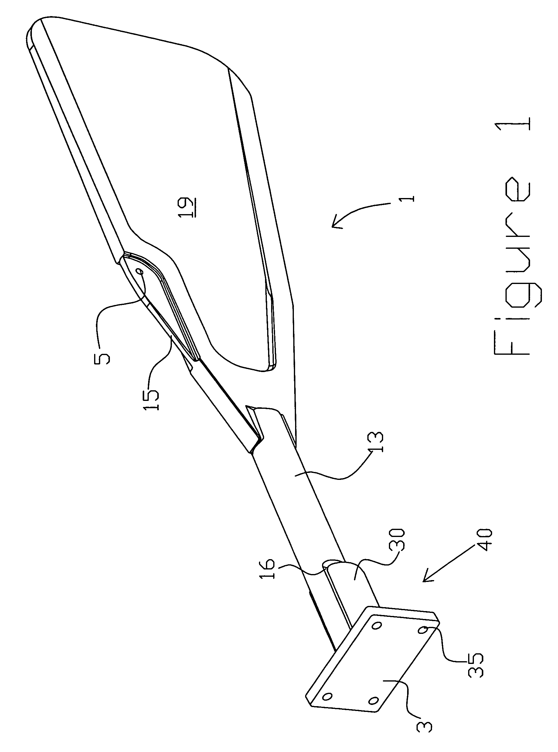
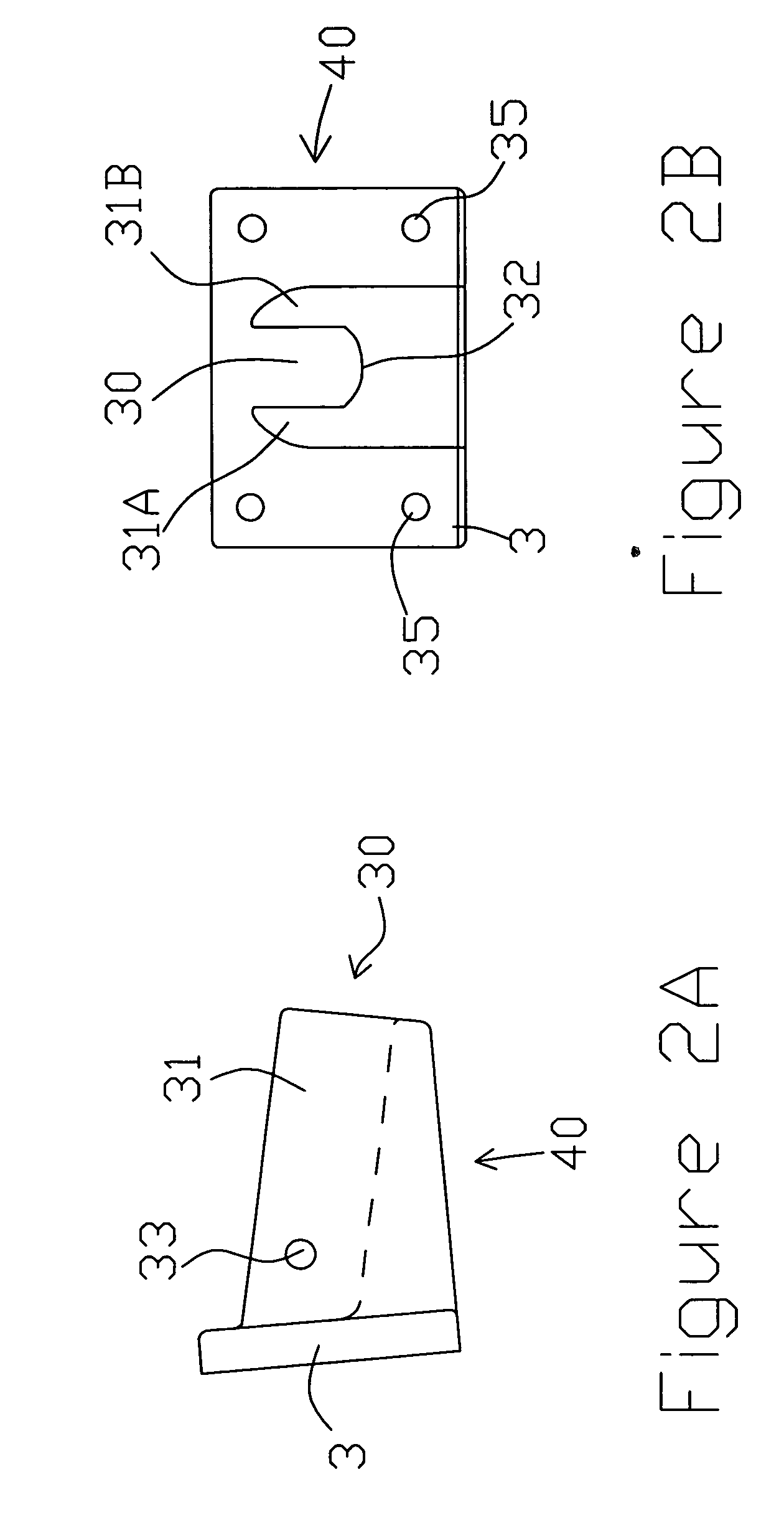
[0029]FIG. 1 is a perspective view of the watercraft stabilizing device 1 of the present invention. The device 1 comprises a mounting device that includes a mounting plate 3 that includes a plurality of mounting holes 35 for passing fasteners such as screws therethrough to fasten the device to a watercraft, preferably a hull of a boat. Trough 30 is integrally formed with the mounting plate 3 in a downward fashion as more clearly shown in FIG. 2A and 2B.

[0030]A first end of handle 13 rests in trough 30. Preferably, handle 13 is generally cylindrical in shape with a cut-out regions 16 more clearly shown in FIG. 3A. Integrally formed at an opposite end of handle 13 is blade 19 more clearly shown in FIGS. 3A and 3B. A thin grip 15 includes a hole 5...


PUM


Abstract

A device for stabilizing boats and other watercraft that is generally blade-shaped and attaches to the body or hull of the boat. The stabilizing device projects generally outwardly and downwardly from the boat and is pivotally connected along the vertical axis at the attachment point to the watercraft. The device dramatically improves the stability of the boat and resists stops unwanted drift either from a stationary position or from a desired heading.

Description

[0001]This application claims the benefit of U.S. Provisional Patent Application No. 60 / 442,979, filed Jan. 28, 2003 and is a continuation-in-part of Application Ser. No. 10 / 761,561, filed Jan. 20, 2004, now abandoned.[0002]This application did not receive any federal research and development funding.BACKGROUND OF THE INVENTION[0003]The present invention relates in general to a stabilizing device for watercraft, and more particularly to watercraft of the type used for water sports such as fishing. Even more particularly this invention relates to a stabilizing device that is attachable to a watercraft in such a manner as to prevent drifting or moving off course as a result of natural or unnatural forces, particularly the effects of currents and wind upon a watercraft that is either stationary or moving on a desired heading.[0004]When stationary in or on the surface of a body of water, most water-borne vehicles provide large surface areas along the longitudinal axis that makes the veh...

Claims


Application Information

Patent Timeline
Patent Type & Authority Patents(United States)
IPC IPC(8): B63B3/38B63B39/06B63H25/42B63H25/44
CPCB63B39/062B63H25/44B63H25/42
Inventor WIDLACKI, DON FELIX
Owner WIDLACKI DON FELIX
Why Eureka
Try Eureka