
Muffler having a baffle with angled plates

Active Publication Date: 2006-09-12
COMPX INTERNATIONAL
View PDF14 Cites 37 Cited by
  • Summary
  • Abstract
  • Description
  • Claims
  • Application Information

AI Technical Summary

Benefits of technology

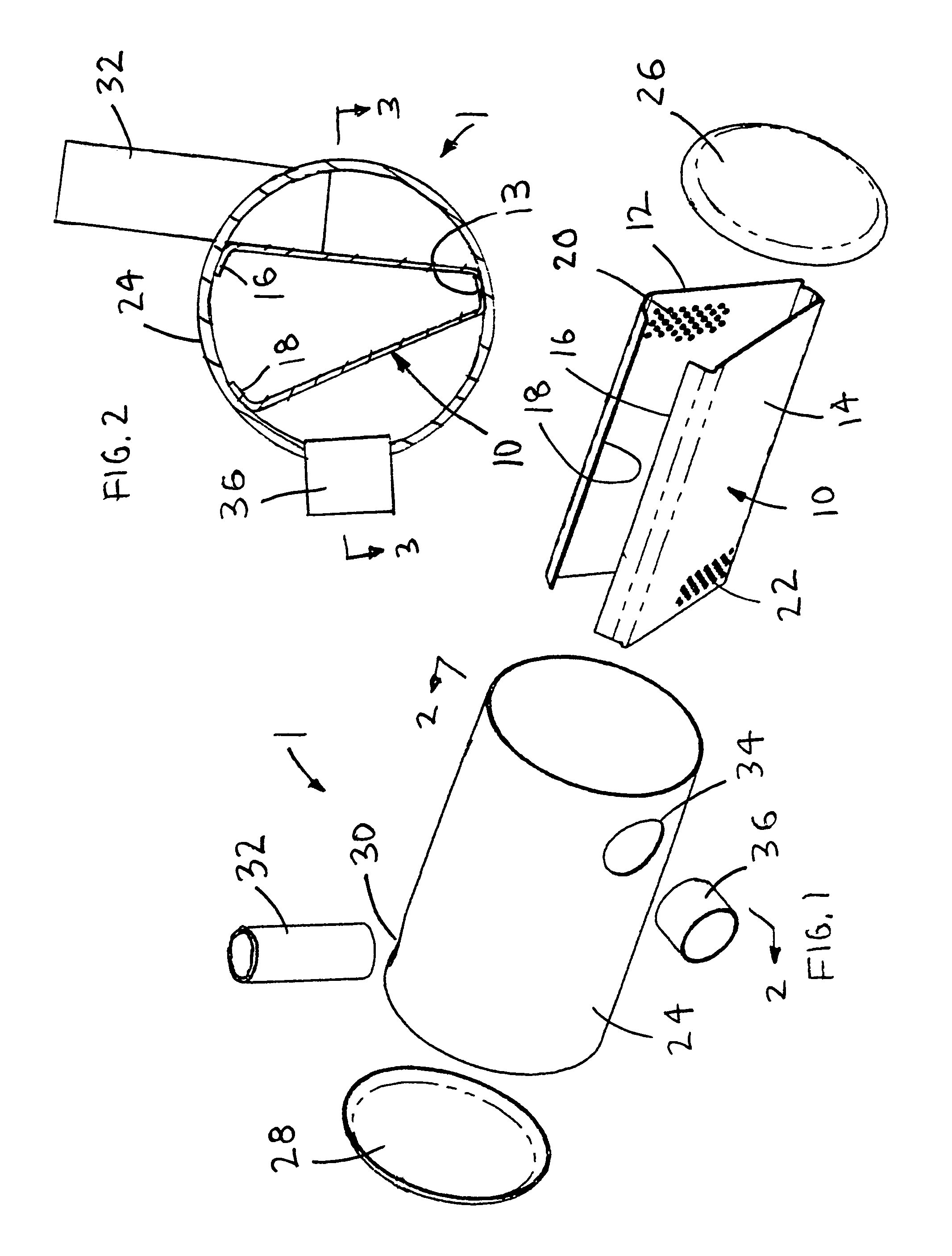
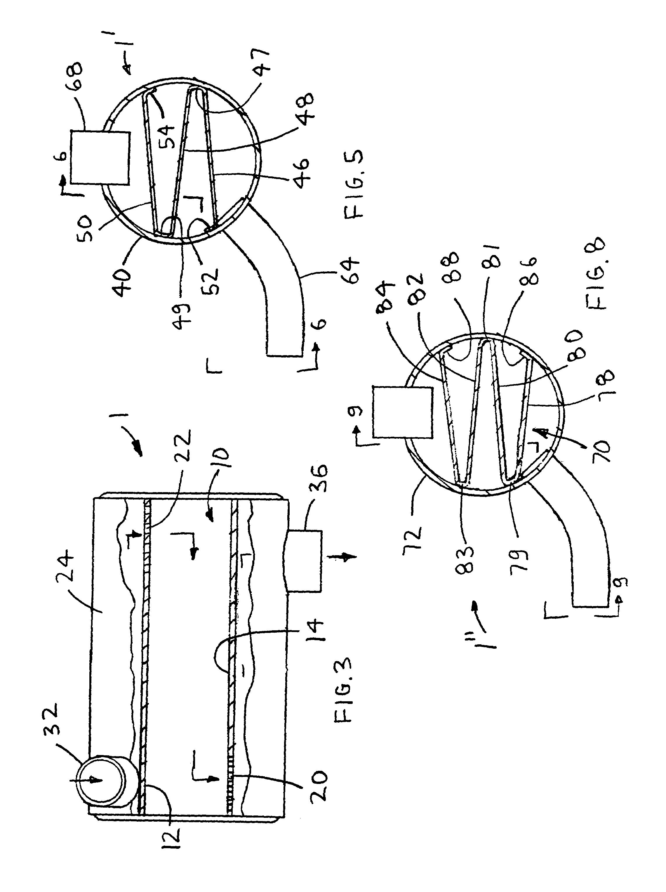
[0006]The present invention provides a muffler having a baffle with angled plates that provides quieter performance. The muffler having a baffle with angled plates (muffler with baffle) includes a one piece baffle, a container and two end caps. The one piece baffle includes at least three different configurations: V, Z and W. The V-baffle includes a single plate bent into two angled plates in the shape of a “V.” The Z-baffle includes a single plate bent into three angled plates in the shape of a “Z.” The W-baffle includes a single plate bent into four angled plates in the shape of a “W.”
[0016]Accordingly, it is an object of the present invention to provide a muffler with baffle, which includes reduced assembly complexity.
[0017]Finally, it is another object of the present invention to provide a muffler with baffle, which includes quieter performance than that of the prior art.

Problems solved by technology

The casing includes a plurality of corrugations, which would require expensive tooling to produce.

Method used


Image

  • Muffler having a baffle with angled plates
  • Muffler having a baffle with angled plates
  • Muffler having a baffle with angled plates

Examples


fifth embodiment

[0084]With reference to FIGS. 31–33a, the muffler with baffle 5′″ includes a one piece combination baffle-container 213, at least two partitions, two end caps 215, the at least two inlet tubes, at least one outlet tube 218 and at least three balance tubes. A baffle with a “Z” configuration is shown in FIG. 33a, but other configurations such as “V” or “W” may also be used. The one piece combination baffle-container 213 includes a baffle portion 225 and a container portion 227.

[0085]A first chamber 223 is formed in the area bounded by a first partition 219, one of the end caps 215 and the baffle portion 225, 243. A second chamber 229 is formed in the area bounded by a second partition 231, the other end cap 215 and the baffle portion 225, 243. A middle chamber 233 is formed between the first and second partitions and the baffle portion 225, 243. A first balance tube 235 is inserted through and secured to the first partition 219 to connect the first chamber 223 to the middle chamber 23...

sixth embodiment

[0088]With reference to FIGS. 34–35, the muffler with baffle 6 includes a one piece corrugated baffle 238, a container 240, two end caps 242, at least one inlet tube 244, and at least one outlet tube 246. Each baffle leg 248 of the corrugated baffle 238 includes openings to allow exhaust flow therethrough. The openings include perforations and / or louvers. The one piece corrugated baffle 238 is retained in the container with welding or any other suitable process. The container 240 is terminated by attaching a single end cap 242 to each end thereof. The container 240 preferably has a tubular construction. The at least one inlet tube 244 is inserted through and secured to a wall of the container 240. The at least one outlet tube 246 is inserted through and secured to a wall of the container 240, substantially opposite the at least one inlet tube 244.


PUM

PropertyMeasurementUnit
Timeaaaaaaaaaa
Angleaaaaaaaaaa
Flow rateaaaaaaaaaa

Abstract

A muffler having a baffle with angled plates includes a one piece baffle, a container and two end caps. The one piece baffle has at least three different configurations. The baffle preferably has two, three or four plates, namely “V”, “Z” or “W” shapes. Each one piece baffle configuration includes openings to allow exhaust flow therethrough. Each one piece baffle configuration is retained in the container. The container is terminated with end caps on each end thereof. At least one inlet tube and at least one outlet tube are attached to a perimeter of the container. In a second embodiment, the container and baffle are formed from a single piece of material. In a third and fourth embodiment, the inlet and outlet tubes are inserted through plates of the baffle. In a fifth embodiment, balanced tubes and chambers are added. In a sixth embodiment, a corrugated baffle is used.

Description

BACKGROUND OF THE INVENTION[0001]1. Field of the Invention[0002]The present invention relates generally to mufflers and more specially to a muffler having a baffle with angled plates that reduces assembly complexity.[0003]2. Discussion of the Prior Art[0004]The prior art provides numerous designs of engine mufflers. Some of these prior art mufflers include U.S. Pat. No. 3,100,140 to Ashley et al., U.S. Pat. No. 5,196,655 to Woods and U.S. Pat. No. 6,415,889 to Wyatt. The Ashley et al. patent discloses a catalytic automotive exhaust converter. The converter is fabricated from a single casing, two end caps, an inlet pipe and an exhaust pipe. The casing includes a plurality of corrugations, which would require expensive tooling to produce. The Woods patent discloses a muffler for a marine engine. The muffler includes two baffle components, a can, two end caps, an inlet pipe and an outlet pipe. The Wyatt patent includes a formed piece of metal and two end caps. First and second serpenti...

Claims


Application Information

Patent Timeline
IPC IPC(8): F01N7/18B21D51/16F01N1/02B21D51/06B21D51/10B23P17/02F01N1/08F01N13/18
CPCF01N1/083F01N1/084F01N1/089F01N13/1872Y10T29/49398F01N2470/18F01N2490/08
Inventor ZELINSKI, JOSEPH R.
Owner COMPX INTERNATIONAL
Learn More