Vibration damper with stroke-dependent damping force

a technology of vibration damper and damping force, which is applied in the direction of vibration damper, shock absorber, spring/damper, etc., can solve the problem of too high cost of certain concrete applications, and achieve the effect of simplifying the design of a vibration damper

Inactive Publication Date: 2006-09-12
ZF FRIEDRICHSHAFEN AG
View PDF22 Cites 10 Cited by
  • Summary
  • Abstract
  • Description
  • Claims
  • Application Information

AI Technical Summary

Benefits of technology

[0007]The advantage here is that the valve disk begins to open sooner than it would in the case of a damping force characteristic with a simple advance opening segment determined by the bypass, and therefore the system is adapted more comfortably overall to the chassis, especially at high piston rod velocities.
[0008]A bypass of simple design consists of a bypass groove. The bypass groove can have an inlet and / or and an outlet with a graduated cross-section. The effective cross-sectional ratios of the bypass groove make it possible for the pressure to change continuously at the second pressure-actuated surface, so that pressure surges which could lead to the sudden opening or closing of the valve are avoided. The bypass groove can be formed by an area of expanded diameter extending around the entire circumference of the cylinder.
[0010]So that the operating behavior can be defined, the sealing sleeve is provided with a seal acting in the direction toward the cylinder. In addition, the gap between the wall of the cylinder and the sealing sleeve is larger than that between the piston and the cylinder, so that any dimensional deviations within the valve as a whole can be compensated. A relatively large gap between the sealing sleeve and the cylinder reduces the throttling action inside the gap and improves to the same degree the intended axial movement of the sealing sleeve.
[0011]The piston with its through-channels for both flow directions is very easy to manufacture, because the minimum of one through-channel for the one flow direction of the damping medium is separated from the valve seat surfaces of the minimum of one through-channel for the other flow direction, where the width of the first pressure-actuated surface is determined by the two valve seat surfaces. The valve seats can be provided in the form of elevations either on the valve disk or on the piston. The advantage of having the valve seats on the valve disk is that different damping force characteristics can be provided simply by replacing the valve disk, which is much less expensive to do than replacing an entire piston.
[0012]The channel for the additional pressure-actuated surface can be realized very easily by having the second pressure-actuated surface extend radially outside the valve seat surfaces for the valve disks.
[0019]Alternatively, the valve seat surface which separates the second pressure-actuated surface from the first pressure-actuated surface can be formed by a seal with axial elasticity, which provides a sealing action as a function of the stroke of the valve disk. For this purpose, for example, a ring-shaped seal can be placed on the top surface of the piston, so that the sealing action of the ring-shaped seal will be ensured over a relatively long axial pretensioning distance. Providing the valve seat with a 3-dimensional design of this type simplifies the design of both the valve disk and the piston surfaces.

Problems solved by technology

This expense can be too high for certain concrete applications.

Method used


Image

  • Vibration damper with stroke-dependent damping force
  • Vibration damper with stroke-dependent damping force
  • Vibration damper with stroke-dependent damping force

Examples


Embodiment Construction

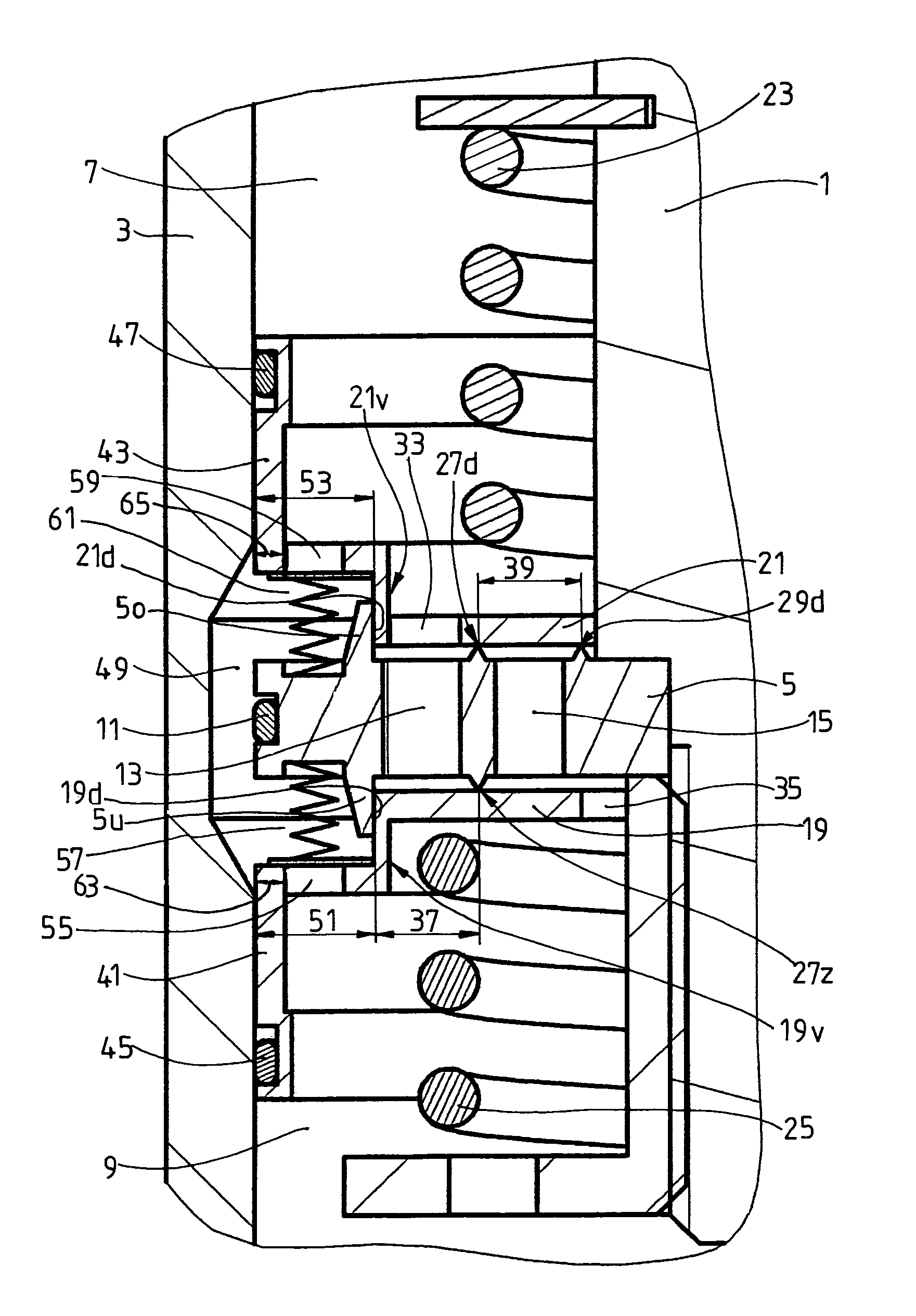
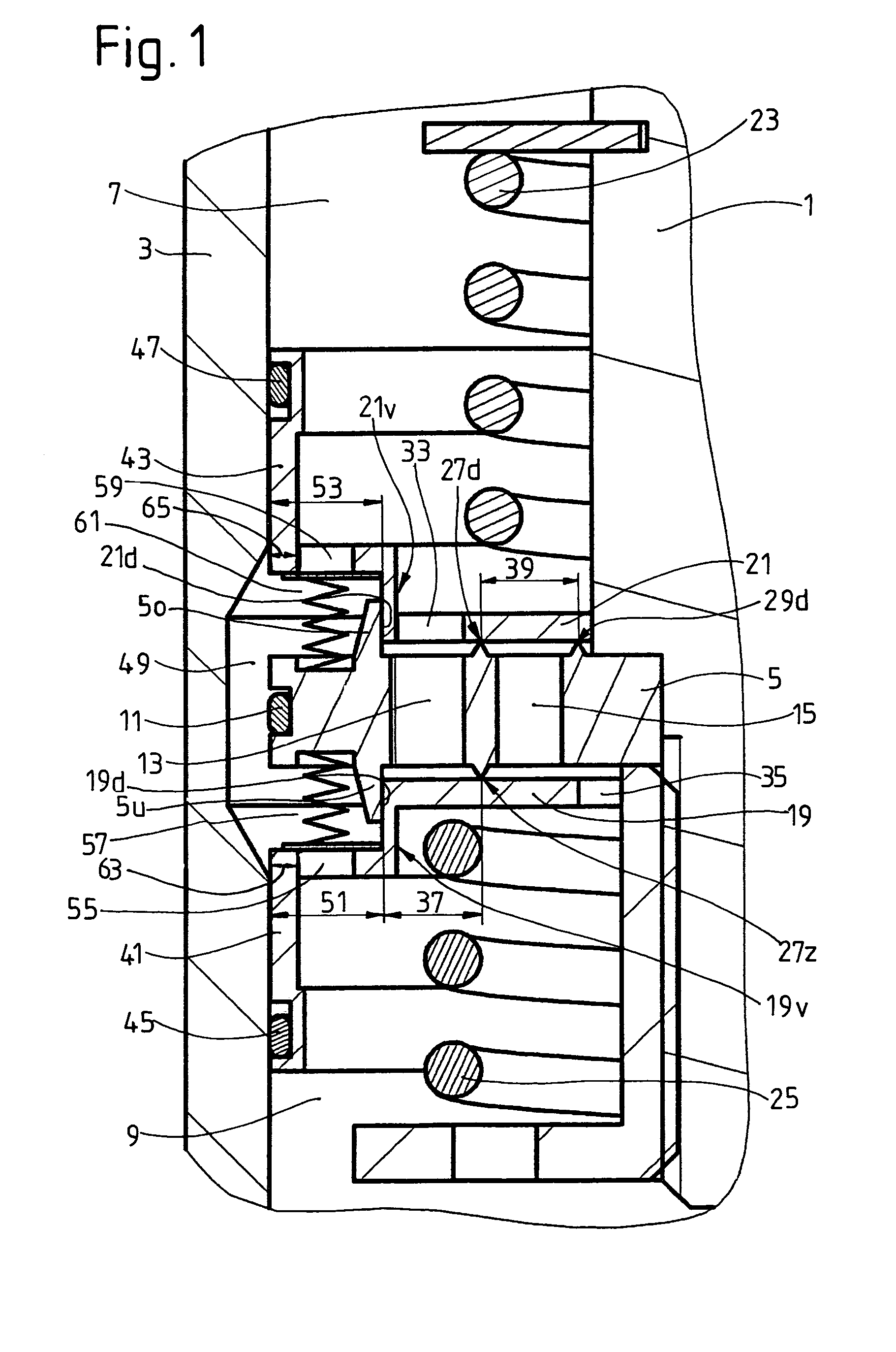
[0024]FIG. 1 shows part of a vibration damper of arbitrary design with the piston rod 1 in an intermediate stroke position with respect to a cylinder 3. The piston rod 1 carries a piston 5, which divides the cylinder into a-working space 7 on the piston rod side and a working space 9 on the side away from the piston rod. A piston ring 11 is mounted in the lateral surface of the piston. Inside the piston, at least one through-channel 13 is provided for the outward travel of the piston rod, and at least one through-channel 15 is provided for the inward travel. The outlet side of the through-channel 13 is covered by a valve disk 19, and that of the through-channel 15 is covered by a valve disk 21. The two valve disks are pretensioned by valve springs 23, 25 onto the valve seat surfaces 27d, 29d, and 27z. A connecting opening 33 aligned with the through-channel 13 is formed in the valve disk 21, and a connecting opening 35 leading to the through-channel 15 is formed in the valve disk 19...


PUM


Abstract

A piston rod with a piston is installed with freedom of axial movement in a damping medium-filled cylinder, where, as a function of the stroke position of the piston, a bypass connects the two working spaces separated from each other by the piston. The piston has at least one through-channel for at least one flow direction, which channel is at least partially covered on the outlet side by at least one valve disk, so that a first pressure-actuated surface to which pressure can be applied in the opening direction is present on the valve disk. In addition to the first pressure-actuated surface, the valve disk has a second pressure-actuated surface, which is separated from the first when the valve disk is closed and which can be actuated via the bypass, in which case the effects of the two pressure-actuated surfaces are additive. The second pressure-actuated surface of the valve disk, in addition to the first pressure-actuated surface of the valve disk, is designed with its throttle point in the area of the second pressure-actuated surface at least during a certain phase of the travel of the valve disk.

Description

BACKGROUND OF THE INVENTION[0001]1. Field of the Invention[0002]The invention pertains to a vibration damper with stroke-dependent damping force of the type having a cylinder filled with damping medium and a piston rod connected to a piston in the cylinder, the piston separating the cylinder into a working space on the piston rod side and a working space away from the piston rod, the piston having at least one first through-channel with a respective at least one outlet for flow in a first direction. A bypass connects the working space on the piston rod side to the working space away from the piston rod as a function of the position of the piston in the cylinder. A first valve disk covers the outlet of the at least one first through-channel, the first valve disk being movable from a closed position to an open position and having a first pressure-actuated surface which is exposed to pressure via said at least one through channel.[0003]2. Description of the Related Art[0004]A piston-cy...

Claims


Application Information

Patent Timeline
Patent Type & Authority Patents(United States)
IPC IPC(8): F16F9/48F16F9/32F16F9/34F16F9/346F16F9/348F16F9/512
CPCF16F9/3214F16F9/3405F16F9/5126F16F9/3487F16F9/346
Inventor HEYN, STEFFENGUNDERMANN, FRANKBOHM, CHRISTIANZEISSNER, BERNDGRUNDEI, MANFRED
Owner ZF FRIEDRICHSHAFEN AG
Why Eureka
Try Eureka