Work support

a workpiece and support technology, applied in the field of workpiece support, can solve the problems of increasing the number of parts, complicating the structure, and insufficient and achieve the effect of reliably retraction and increasing the dependability and reliability of the operation of the workpiece suppor

Inactive Publication Date: 2006-09-12
PASCAL ENG
View PDF13 Cites 7 Cited by
  • Summary
  • Abstract
  • Description
  • Claims
  • Application Information

AI Technical Summary

Benefits of technology

[0012]At this point, the leading end of the rod comes in contact with the workpiece, and the piston member then moves to or near the stroke end thereof, whereupon the hydraulic operating chamber of the hydraulic cylinder is connected with the external peripheral hydraulic chamber via the oil passage. Oil pressure is thereby supplied to the external peripheral hydraulic chamber with the leading end of the rod in contact with the workpiece, the sleeve body is elastically deformed by this oil pressure so as to shrink in diameter, the rod is firmly locked, and the workpiece is reliably supported.
[0014]By means of this workpiece support, particularly because an oil passage is provided for connecting the hydraulic operating chamber of the hydraulic cylinder with the external peripheral hydraulic chamber when the piston member of the rod-driving hydraulic cylinder has moved up to or to the vicinity of the stroke end thereof, the rod is reliably brought into contact with the workpiece, the rod can then be reliably locked, and the dependability and reliability of the operation of the workpiece support can be increased without complicating the structure of the workpiece support.
[0015]In this arrangement, a spring member is preferably provided inside the rod for elastically urging the rod to retract. In this case, by stopping the oil pressure supply from the oil pressure supply source to the hydraulic operating chamber, the rod can be retractably moved by the elastic urging force of the spring member, and the piston member can also be retractably moved together with the rod. Also, a second spring member is preferably provided for connecting the rod to the piston member so as to be capable of relative movement in the axial direction by a prescribed stroke, and for elastically urging the rod forward. The piston member and the rod can thereby be integrally raised so that the leading end of the rod first comes in contact firmly with the workpiece and is maintained in that position, the piston member alone can move to or near the stroke end thereof, and the rod can be reliably locked in place and the workpiece reliably supported, as described above. In this case, a configuration is preferably adopted whereby the piston member is elastically urged to retract by the aforementioned spring member used for retraction movement, and the rod is elastically urged to retract with the aid of the piston member. The piston member can thereby be reliably retracted together with the rod.

Problems solved by technology

However, in this workpiece support,because oil pressure is supplied from a shared oil pressure supply port simultaneously to the pressure intensifier and the rod-driving hydraulic cylinder, the rod tends to lock before making contact with the workpiece, thus creating drawbacks of inadequate dependability and reliability of the operation of the workpiece support.
However, this arrangement has drawbacks because the need for providing a restricting valve and non-return valve increases the number of parts and complicates the structure.

Method used


Image

  • Work support
  • Work support
  • Work support

Examples


Embodiment Construction

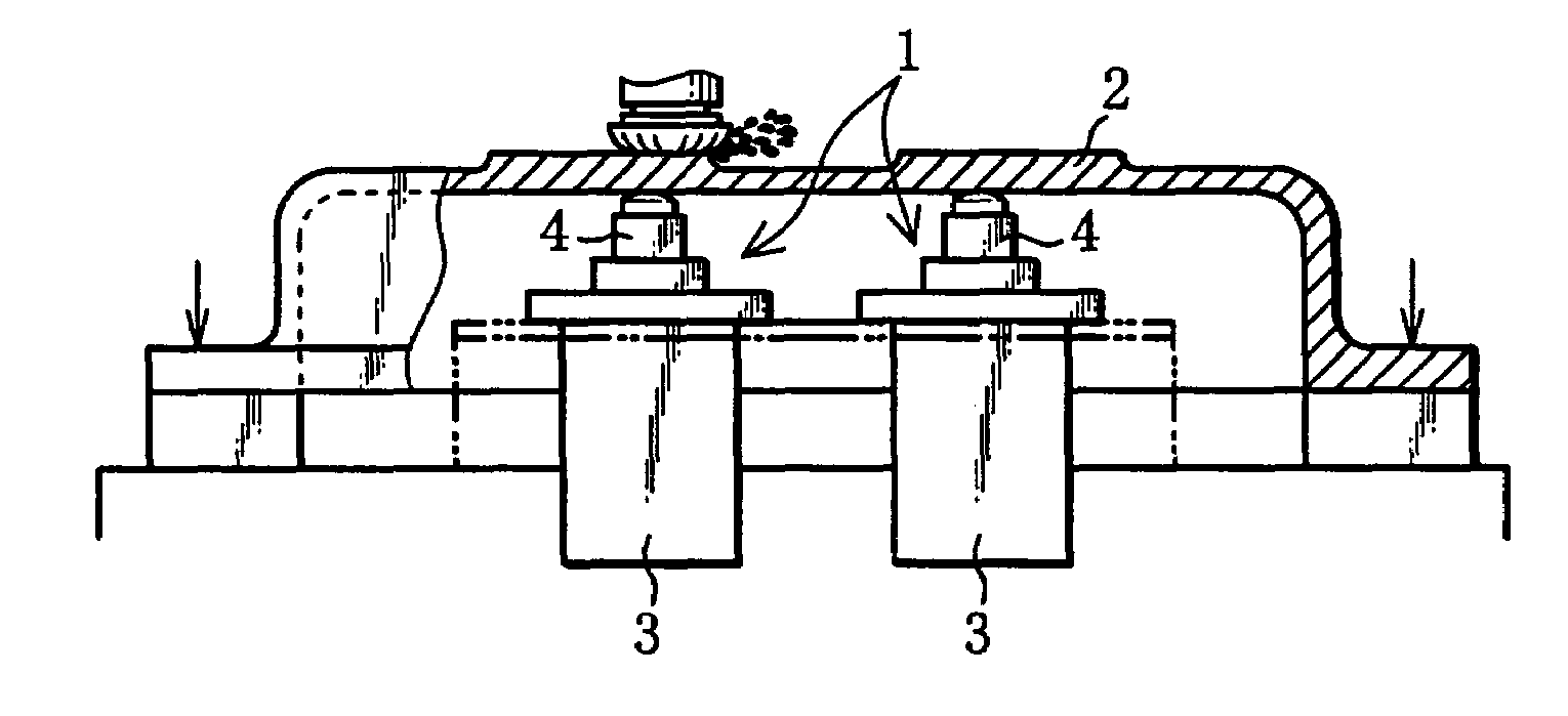
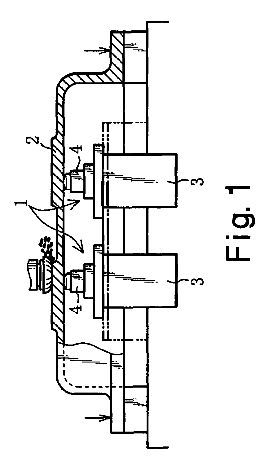
[0019]An embodiment of the present invention will be described hereinafter with reference to the drawings. As shown in FIG. 1, the workpiece support 1 of the present embodiment is for supporting the workpiece 2 from underneath and preventing the workpiece 2 from vibrating during machining.

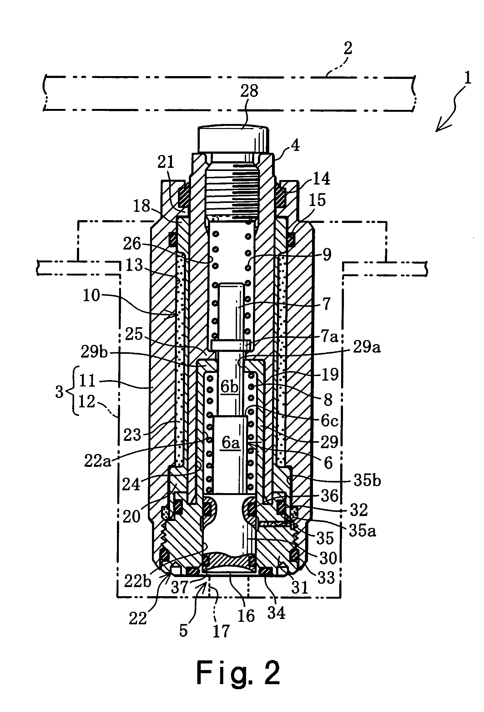
[0020]As shown in FIGS. 2 and 3, the workpiece support 1 has a substantially cylindrical case member 3, a rod 4, a rod-driving hydraulic cylinder 5, shaft members 6, 7, spring members 8, 9, a metal sleeve body 10, and the like.

[0021]The case member 3 is formed so as to open to the outside from the bottom end upwards, and comprises a case main body 11 open at both ends and a case cover 12 externally fitted on and fixed to the case main body 11. A rod-containing hole 13 is formed in the case main body 11, and seal members 14 and 15 are provided therein. The case cover 12 has a closed-end cylindrical structure and a flange portion formed at the top thereof, and is supported at the flange portion by a ...


PUM

PropertyMeasurementUnit
diameteraaaaaaaaaa
pressureaaaaaaaaaa
elastic deformationaaaaaaaaaa

Abstract

A workpiece support has a simplified structure and can operate with improved dependability and reliability. The workpiece support has a rod, a sleeve body externally fitted on the rod and elastically deformable so as to shrink in diameter, a case member supporting the sleeve body, and an external peripheral hydraulic chamber formed on the external periphery of the sleeve body. A hydraulic cylinder is provided for moving the rod in the axial direction and oil passage are provided for connecting the hydraulic operating chamber of the hydraulic cylinder with the external peripheral hydraulic chamber when the piston member of the hydraulic cylinder has moved up to or to the vicinity of the stroke end thereof.

Description

TECHNICAL FIELD[0001]The present invention relates to a workpiece support that is designed so that a sleeve body externally fitted on a rod is elastically deformed by oil pressure, and the rod is locked, and relates particularly to a workpiece support that is improved so as to increase the reliability and dependability of the operation of the workpiece support.BACKGROUND OF THE INVENTION[0002]Workpiece supports for supporting workpiece from underneath have been provided for cutting workpiece and the like, and the present applicant has also proposed and submitted patent applications for various workpiece supports (Japanese Patent Application Nos. H11-46922, 2000-84112, and others).[0003]The workpiece support in Japanese Patent Application No. H11-46922 has a case member, a rod, a rod-moving hydraulic cylinder, a sleeve body, a pressure intensifier, an outer peripheral hydraulic chamber, and the like.[0004]The sleeve body is configured so as to be capable of elastic deformation and is...

Claims


Application Information

Patent Timeline
Patent Type & Authority Patents(United States)
IPC IPC(8): B23G3/08B23Q1/76B23Q3/02B23Q5/26B66F3/24B66F3/30F15B15/26
CPCB23Q5/26B23Q1/76F15B15/262
Inventor KITAURA, ICHIRO
Owner PASCAL ENG
Why Eureka
Try Eureka