Wheeled type working vehicle

Inactive Publication Date: 2006-09-12
HITACHI CONSTR MASCH CO LTD
View PDF59 Cites 16 Cited by
  • Summary
  • Abstract
  • Description
  • Claims
  • Application Information

AI Technical Summary

Benefits of technology

[0039]By adopting the structure described above, the quantity of oil that is leaked from the hydraulic cylinder is minimized, to prevent the upper swiveling body from being lowered to an undesirable extent.
[0040]It may be further provided with a retaining member that is utilized to operate the stop va

Problems solved by technology

In addition, the pin used to restrict the movement of the axle relative to the body slides along the vertical direction as the axle moves up and down, hastening the process in which the sliding area becomes worn.
As a result, the play of the pin in the long hole increases, which causes a displacement of the axle relative to the body along the horizontal direction as well as along the vertical direction, thereby making it difficult to smoothly absorb an impact.
Furthermore, since single-acting hydraulic cylinders are utilized, which are engaged only when they contract, an impact cannot be hydraulically absorbed while they are extended, allowing the impact to be applied to the component members.
Thus, the work ve

Method used


Image

  • Wheeled type working vehicle
  • Wheeled type working vehicle
  • Wheeled type working vehicle

Examples


first embodiment

[0065

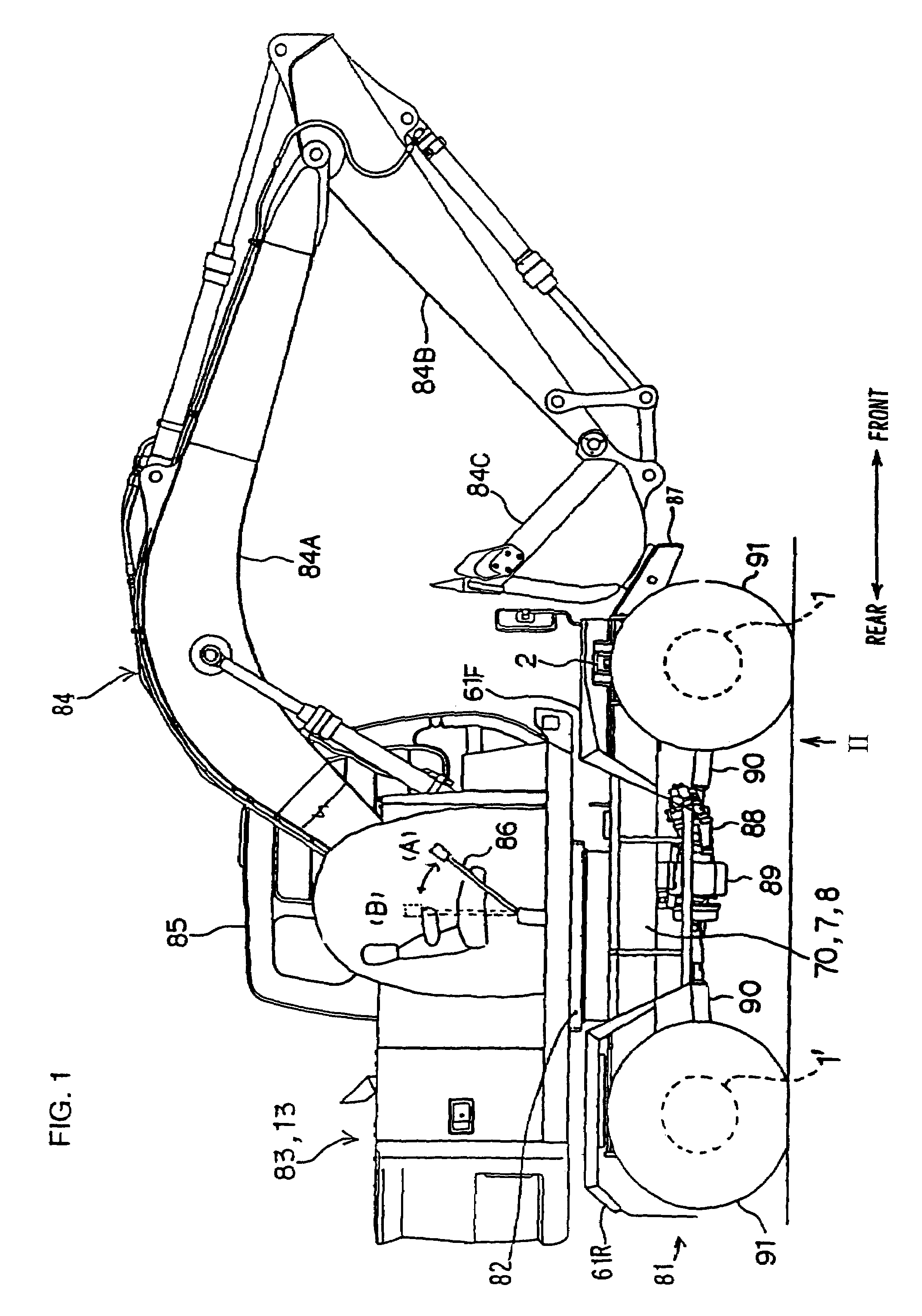
[0066]FIG. 1 is a side elevation (a partial sectional view) of a wheeled hydraulic excavator in which the present invention is adopted. As illustrated in FIG. 1, the wheeled hydraulic excavator includes a lower travelling body 81 and an upper swiveling body 83 which is rotatably linked to the top of the lower travelling body 81 via a swiveling device 82. At the upper swiveling body 83, a front attachment 84 (hereafter referred to as an attachment) constituted of a boom 84A, an arm 84B and a bucket 84C and an operator's cab 85 are provided, with a gate lock lever 86 which is operated to a release position (position A) when the operator boards the vehicle and is operated to a locked position (position B) when the operator leaves the vehicle provided at the entrance of the operator's cab 85. A chassis frame 70 (hereafter referred to as a frame), a travelling hydraulic motor 88, a transmission 89, a propeller shaft 90 and tires 91 are provided at the lower travelling body 81, and t...

second embodiment

[0118

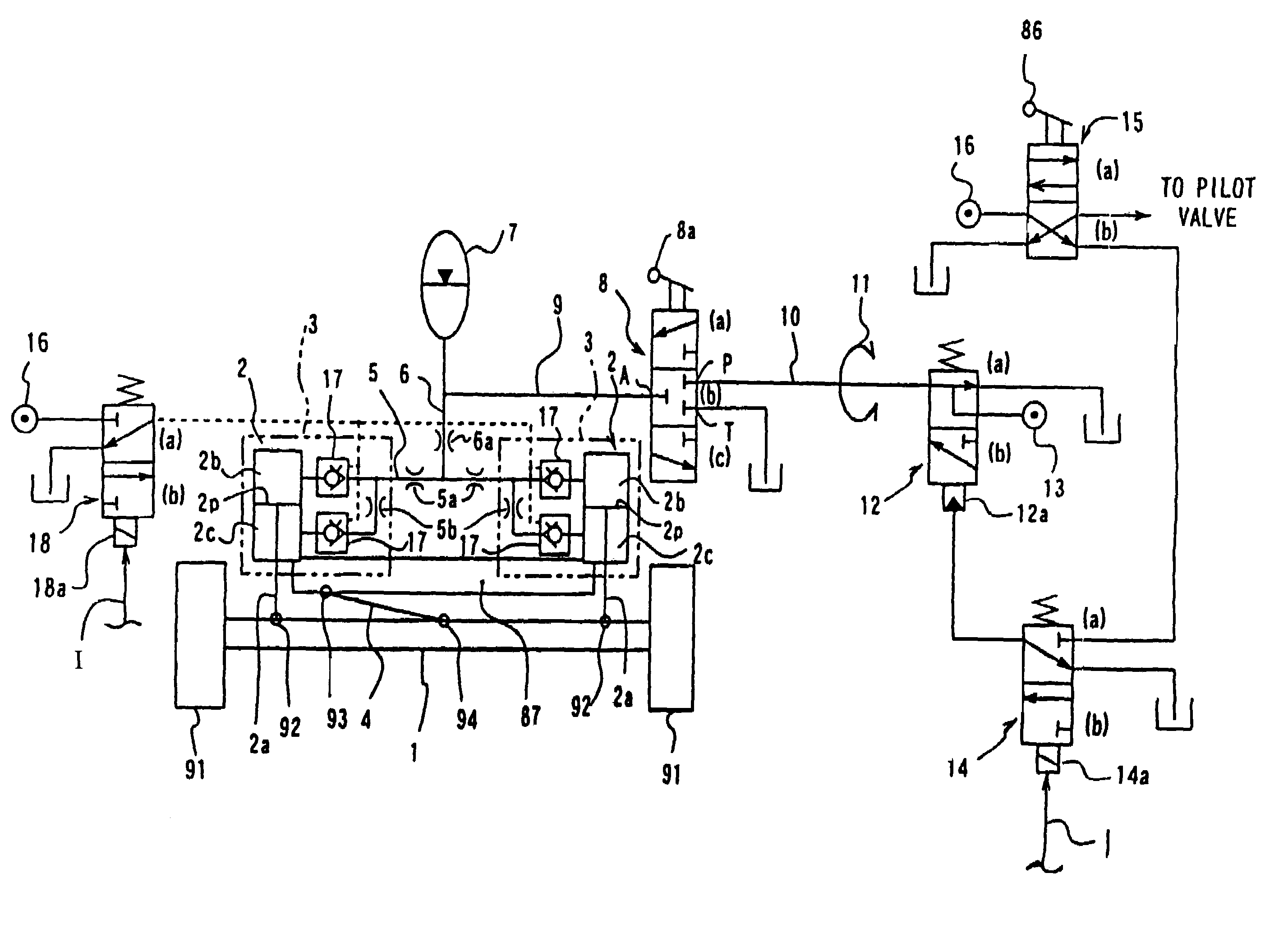
[0119]FIG. 18 is a hydraulic circuit diagram illustrating the structure of the leveling device achieved in the second embodiment of the present invention. It is to be noted that the same reference numerals are assigned to components identical to those shown in FIG. 11 and the following explanation mainly focuses on the differences from FIG. 11. As shown in FIG. 18, the leveling device in the second embodiment is constituted by providing an solenoid control valve 31 that controls the flow of the pressure oil from the main hydraulic source 13 to the individual hydraulic cylinders 2, a controller 30 that controls the drive of the solenoid control valve 31, stroke sensors 32 and 33 that detect the stroke distances z1 and z2 of the hydraulic cylinders 2 from a reference position z0 (corresponds to the state shown in FIG. 16A in the embodiment) and a gate lock switch 86a that is turned on / off in response to a release / lock operation of the gate lock lever 86, in place of the direction...


PUM


Abstract

The wheeled work vehicle according to the present invention has a link that links at least either one of the axles and provided at the front and the rear of the vehicle to a body, suspension hydraulic cylinders provided at the left side and the right side of the chassis to link the axle to the body in conjunction with the link and an accumulator that is made to communicate with oil chambers and of the hydraulic cylinders via restrictors.

Description

[0001]This is a Continuation of application Ser. No. 09 / 890,854 filed Aug. 7, 2001, now U.S. Pat. No. 6,820,877 which in turn is a National Stage of PCT / JP00 / 00715 filed Feb. 9, 2000. The entire disclosure of the prior applications are hereby incorporated by reference herein in its entirety.INCORPORATION BY REFERENCE[0002]The disclosures of the following priority applications are herein incorporated by reference:[0003]Japanese Patent Application No. H11-031732[0004]Japanese Patent Application No. H11-036047[0005]Japanese Patent Application No. H11-036048[0006]Japanese Patent Application No. H11-036049[0007]Japanese Patent Application No. H11-036050[0008]Japanese Patent Application No. H11-031733[0009]Japanese Patent Application No. H11-040164BACKGROUND OF THE INVENTION[0010]1. Field of Invention[0011]The present invention relates to a wheeled work vehicle that travels on tires.[0012]2. Description of Related Art[0013]In order to improve the comfort of the operator driving a work veh...

Claims


Application Information

Patent Timeline
IPC IPC(8): B60G17/00B60G9/02B60G11/30B60G17/005B60G17/015B60G17/056E02F9/22
CPCB60G9/02B60G11/30B60G17/005B60G17/015B60G17/056E02F9/2257E02F9/2217B60G2200/30B60G2200/341B60G2204/46B60G2300/06B60G2400/252B60G2200/32
Inventor ICHIMURA, KAZUHIROTSUKUI, HIROSHITATSUNO, YUKIHIRO
Owner HITACHI CONSTR MASCH CO LTD
Why Eureka
Try Eureka