Projection lens for light source arrangement

a technology of projection lens and light source, applied in the field of projection lens, can solve the problems of merely providing limited effect, affecting and reducing the lighting intensity of the light beam, so as to improve the lighting intensity of light beams emitted

Inactive Publication Date: 2006-09-12
CHEN AMY YUN
View PDF3 Cites 95 Cited by
  • Summary
  • Abstract
  • Description
  • Claims
  • Application Information

AI Technical Summary

Benefits of technology

[0007]A main object of the present invention is to provide a projection lens for light source arrangement which can substantially enhance the lighting intensity of the light beams emitted from the light source therefore.
[0008]Another object of the present invention is to provide a projection lens for light source arrangement, which is capable of effectively converging, by virtue of a predetermined pattern of diffraction, diverging light beams emitted from one or more single light sources, such as LED, to form a high intensity, coherent and high quality light effect having an accurate projection angle.
[0009]Another object of the present invention is to provide a light source arrangement having a projection lens that converges diverging light beams emitted from a single light source by total internal reflections such that no reflective coating is required.
[0010]Another object of the present invention is to provide a projection lens for light source arrangement, which employs simple diffraction theory to a lens body to effectively reflect otherwise diverging light beams emitted from a single point of light source or gathering points of light sources into a coherent, high quality and converging light source arrangement. In other words, no coating is required.
[0012]Another object of the present invention is to provide a projection lens for light source arrangement, which is capable of providing a 100% of reflective efficiency while the aluminum coated reflective surface can generally provide a 70% reflective efficiency. Generally speaking, the projection lens of the present invention enhances the reflective efficiency for about 30% in comparison with the conventional metallic coated reflective surface.
[0013]Another object of the present invention is to provide a light source arrangement, which is simple in structure, easy to manufacture, convenient to use and does not involve complicated electronics, so as to minimize manufacturing and the ultimate selling price of the present invention.

Problems solved by technology

As a result, various practical applications which are traditionally performed by expensive and non-reliable light sources, such as advertisement signs and interior / exterior decoration lighting, have been gradually replaced by LEDs applications.
However, such reflection coating surface merely can provide limited effect and generally has to position behind the LED.
Moreover, during the electrolytic coating process of the reflective surface, environmental pollutants, waste water and other poisonous materials are produced too.

Method used


Image

  • Projection lens for light source arrangement
  • Projection lens for light source arrangement
  • Projection lens for light source arrangement

Examples


Embodiment Construction

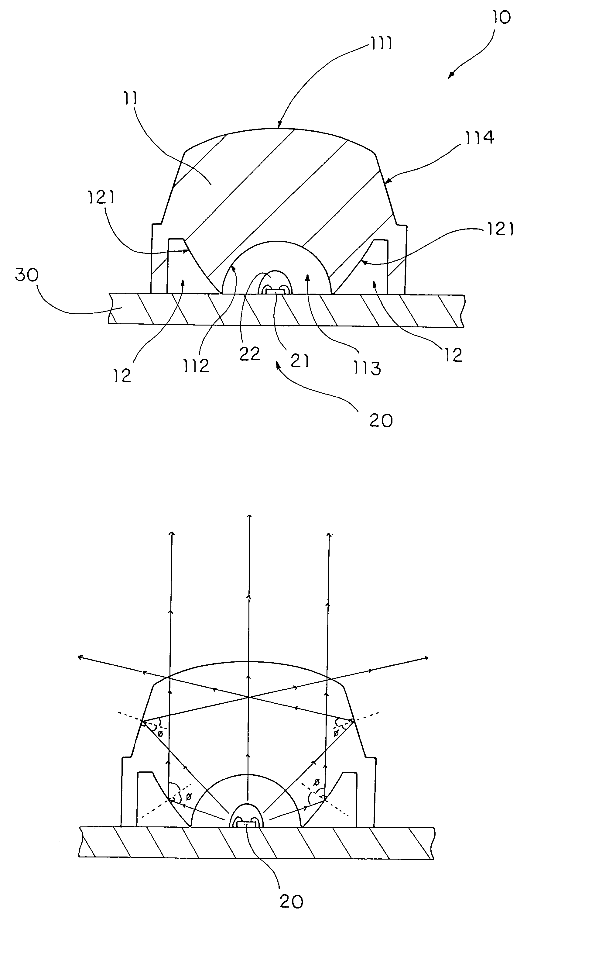
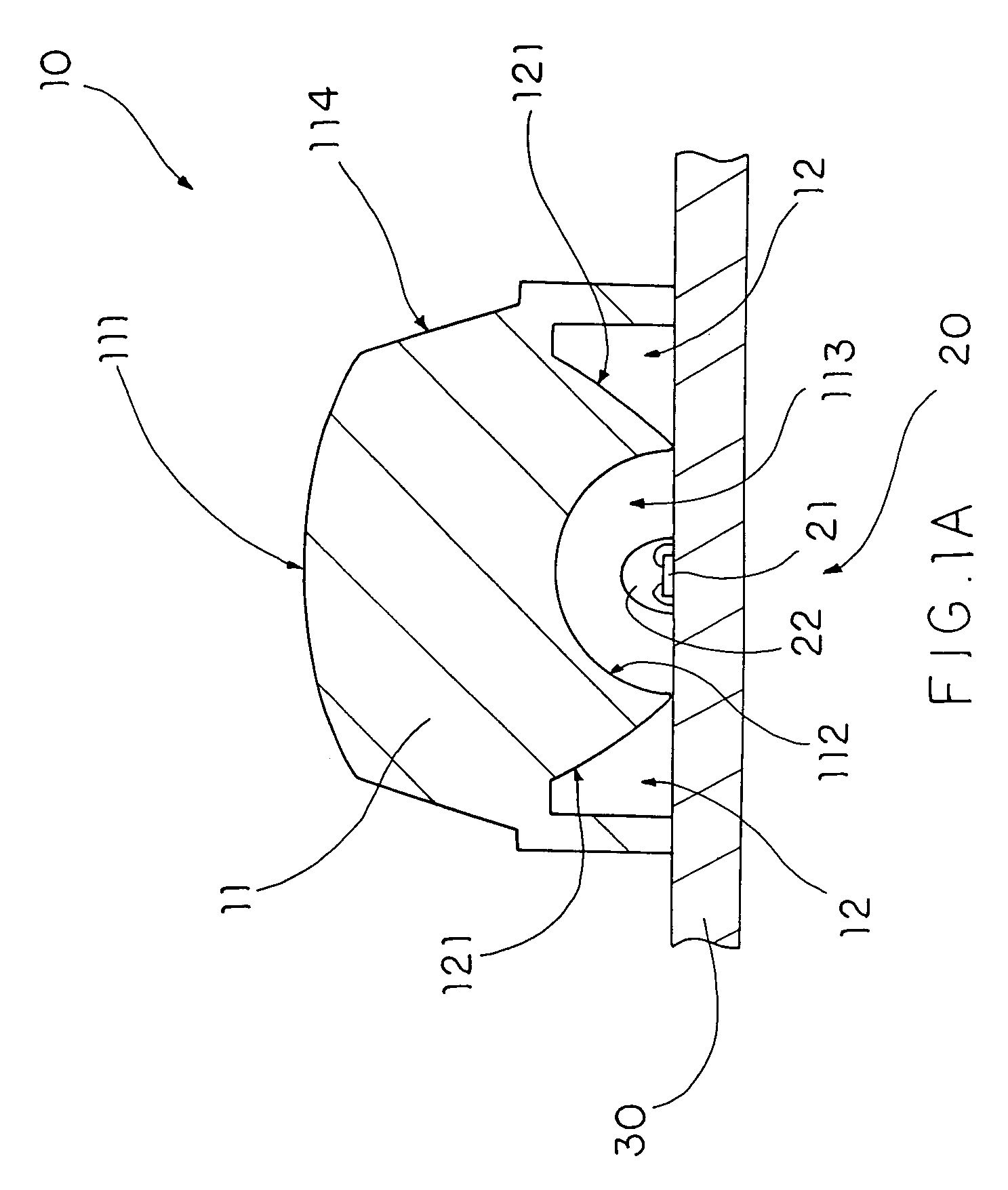
[0022]Referring to FIGS. 1A and 1B of the drawings, a light source arrangement according to a preferred embodiment of the present invention is illustrated, in which the light source arrangement comprises at least a lens body 10 and an illumination unit 20.

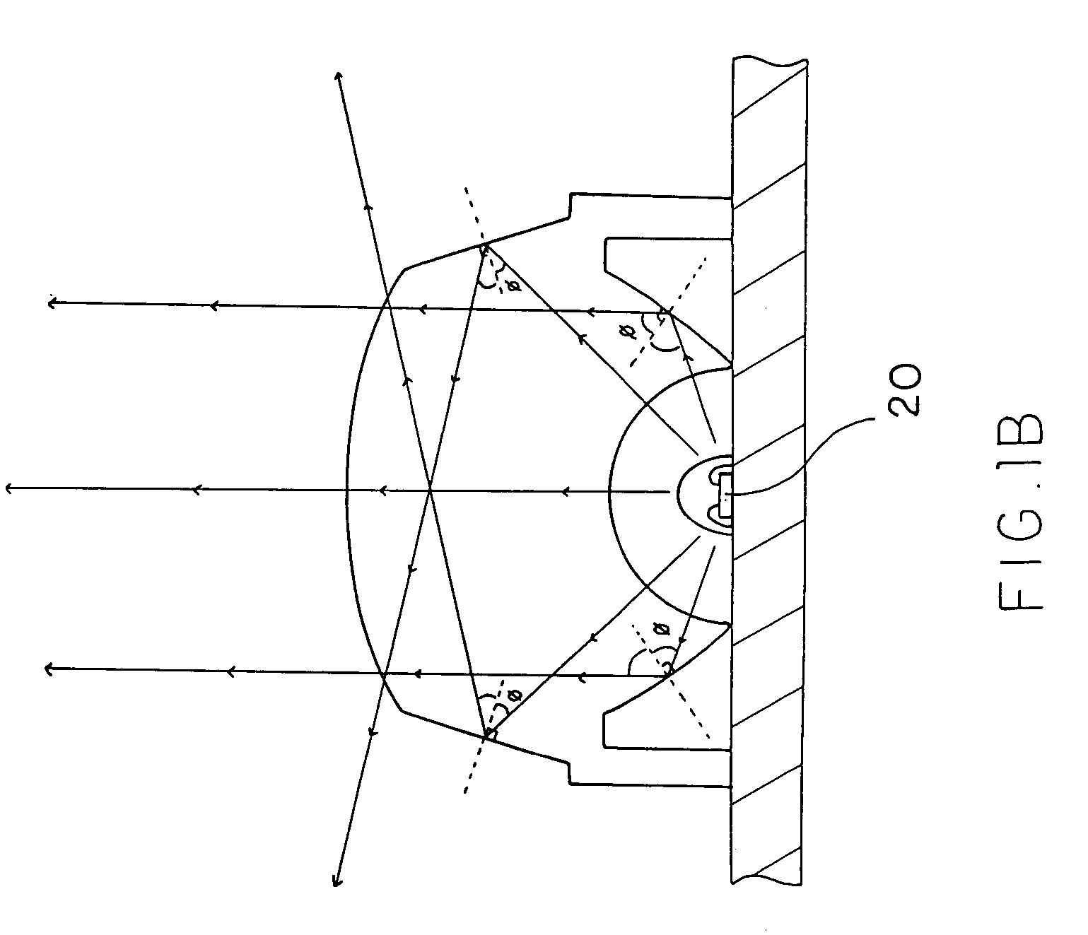
[0023]The lens body 10 has an illumination portion 11 defining a light projecting surface 111 and a light receiving surface 112, and at least a diffraction portion 12 defining a light diffraction surface 121 inclinedly extended at a diffraction angle φ from the light receiving surface 112 of the illumination portion 11, wherein a diffraction density of the illumination portion 11 is different from that of the diffraction portion 12.

[0024]The lens body 10 covers the illumination unit 20 that radially generates light towards the light receiving surface 112. A first portion of the light emitted from the illumination unit 20 penetrates through the illumination portion 11 to the light projecting surface 111 thereof while a second portio...


PUM


Abstract

A light source arrangement for substantially enhaning the lighting intensity of the light beams emitted from the light source therefore includes a lens body and an illumination unit. The lens body has an illumination portion defining a light projecting surface and at least a diffraction portion defining a light diffraction surface inclinedly extended at a diffraction angle, wherein a diffraction density of the illumination portion is different from that of the diffraction portion. The illumination unit is covered by the lens body for radially generating light towards the illumination portion. When the light reaches the light diffraction surface of a diffraction portion at an angle larger than the diffraction angle, the light is substantially reflected at the light diffraction surface back towards the light projecting surface, such that the light from the illumination unit is converged to project at the light projecting surface of the lens body.

Description

BACKGROUND OF THE PRESENT INVENTION[0001]1. Field of Invention[0002]The present invention relates to a lens, and more particularly to a projection lens which is capable of effectively converging, by virtue of a predetermined pattern of diffraction, diverging light beams emitted from a single light source, such as a LED, to form a high intensity, coherent and high quality light effect having an accurate projection angle.[0003]2. Description of Related Arts[0004]LED (Light Emitting Diode) has been widely utilized as an efficient and comparatively economical light source for providing illumination in different surrounding circumstances. For example, a plurality of LEDs may be electrically connected to form rope light, indication light source, Christmas light string, advertisement sign board, and etc. Different combinations of LEDs of differing colors may be arranged in a particular manner such that numerous light effects can be generated for differing applications.[0005]Over the years,...

Claims


Application Information

Patent Timeline
Patent Type & Authority Patents(United States)
IPC IPC(8): F21V7/00F21V11/02
CPCF21V5/04F21V7/0091G02B5/1861G02B19/0061G02B19/0028G09F13/22F21W2101/02H01L33/58H01L33/60F21W2107/10
Inventor ZHANG, LONG BAO
Owner CHEN AMY YUN
Why Eureka
Try Eureka