Radiographic apparatus

a radiographic apparatus and cassette technology, applied in the field of cassette radiographic apparatus, can solve the problems of electronic parts, semiconductor sensors, damage to electronic parts, etc., and achieve the effects of reducing the degree of freedom of radiographing, high portability, and discomfort for subjects

Inactive Publication Date: 2006-09-12
CANON KK
View PDF34 Cites 35 Cited by
  • Summary
  • Abstract
  • Description
  • Claims
  • Application Information

AI Technical Summary

Benefits of technology

[0018]An object of the present invention is to provide a radiographic apparatus which solves the above-described problems, and which has high portability, with discomfort to a subject and decrease in the degree of freedom of radiographing being suppressed.

Problems solved by technology

When compared to a conventional photosensitive-film-built-in cassette, there is a possibility that as the weight increases, such an electronic cassette will be destroyed if it is inadvertently dropped.
However, when a specific portion of the subject is to be radiographed from a specific direction, for example, when the electronic cassettes 1′ and 1″ are held under the arm of the subject S as shown in, for example, FIG. 12, problems arise in that the handles 9 and 10 become obstacles to the subject S or the presence of the handles 9 and 10 makes it difficult to place the electronic cassette at a desired position.
In particular, in the case of the electronic cassette, an important consideration is that there is a possibility that electronic parts, including semiconductor sensors, will be damaged by external impact.

Method used


Image

  • Radiographic apparatus
  • Radiographic apparatus
  • Radiographic apparatus

Examples


first embodiment

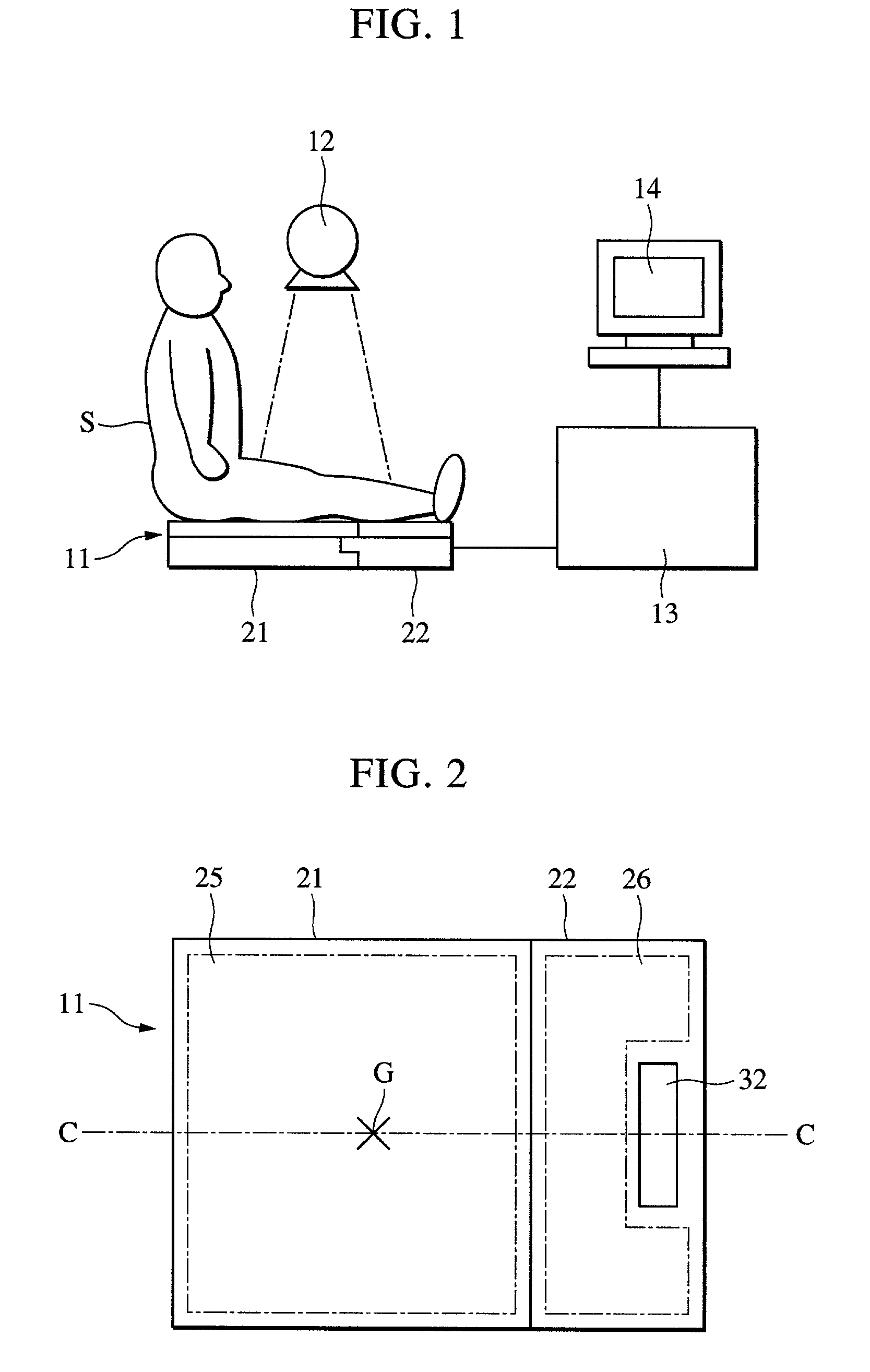
[0040]The present invention will now be described in detail with reference to the embodiments shown in FIGS. 1 to 10. FIG. 1 shows the construction of an X-ray imaging system, in which an electronic cassette 11 as an X-ray imaging apparatus of the first embodiment is horizontally disposed on a floor, etc., and an X-ray generation device 12 is disposed above the electronic cassette 11. Image processing means 13 for processing image signals is connected to the electronic cassette 11, and a monitor 14 for displaying an X-ray image is connected to the image processing means 13.

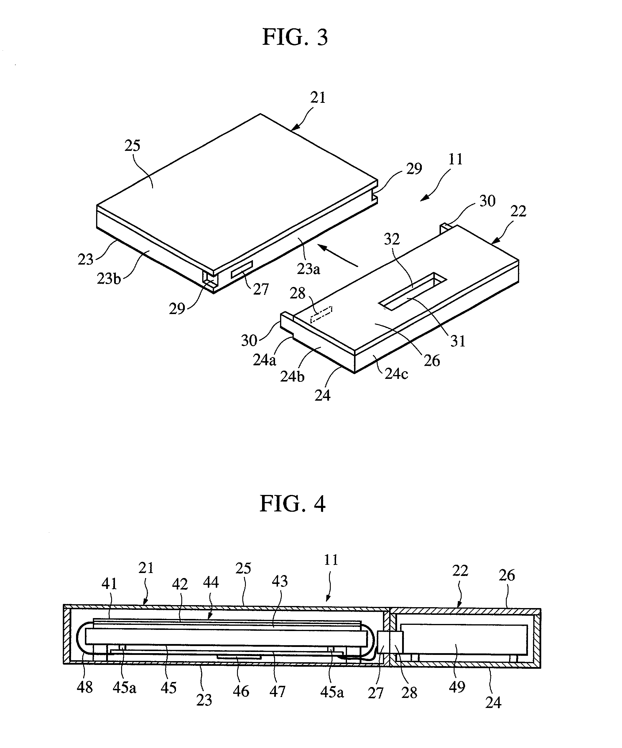
[0041]FIG. 2 is a plan view of the electronic cassette 11. FIG. 3 is an exploded perspective view of the electronic cassette 11, which can be separated / coupled, and which has a first housing 21 and a second housing 22, both of which are rectangular parallelepipeds. The housings 21 and 22 are symmetrical with respect to the center line C—C, the same in thickness with respect to the center line C—C, and the top and ...

fifth embodiment

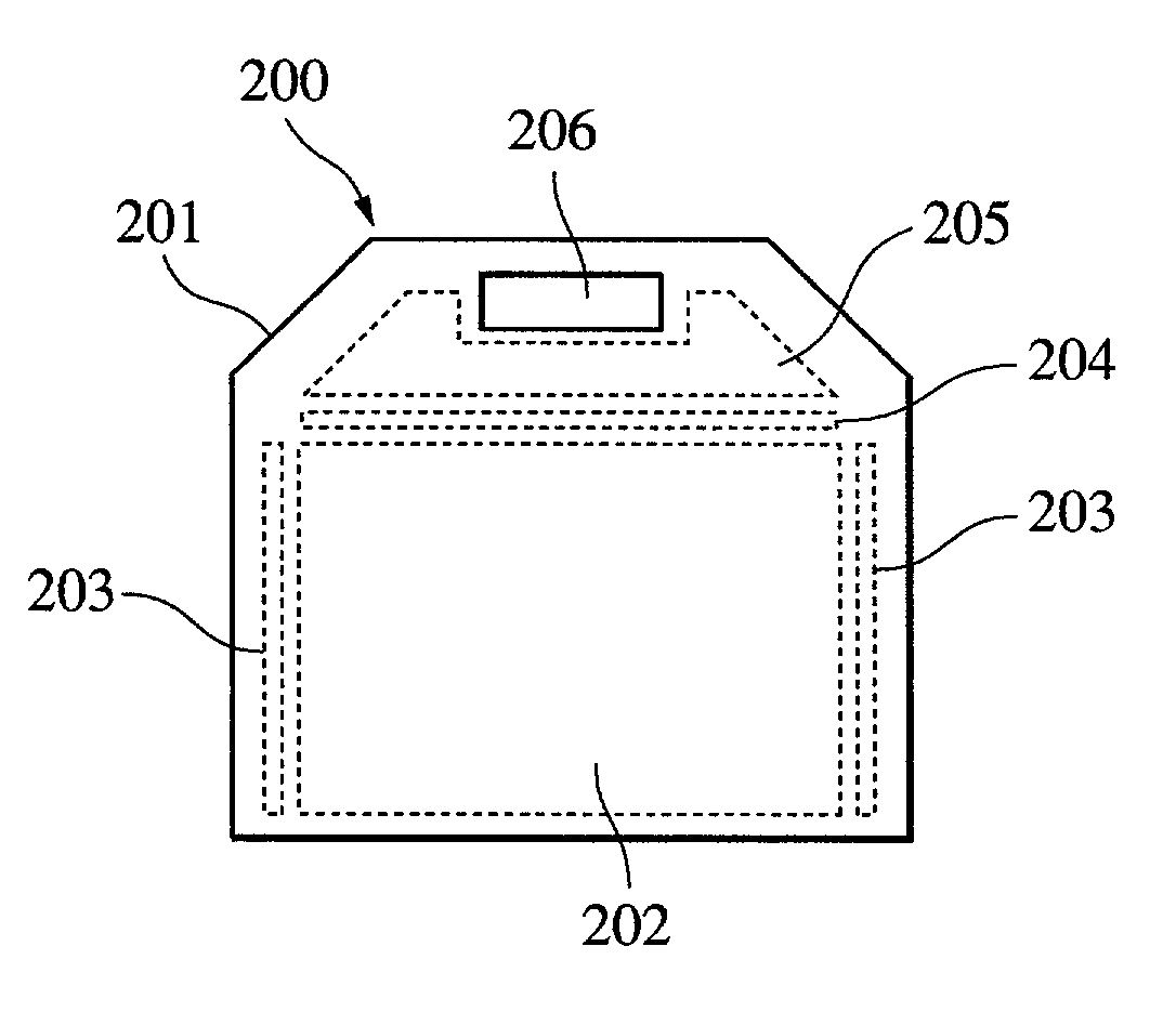
[0075]As described above, in the fifth embodiment, as a result of disposing a handle on the longer side of the X-ray detection panel 202 whose detection surface is rectangularly formed, sensor driving with a high S / N ratio can be realized, and an adverse influence of electromagnetic noise which is generated by the power source can be reduced. In a case where a photograph is taken while the electronic cassette is held by the subject, in most cases, when, in particular, the electronic cassette is held oblong, it becomes easy to hold the electronic cassette by the subject by hand.

[0076]FIG. 10 is a plan view of an electronic cassette 200′ of a sixth embodiment of the present invention. Components which are the same as those of the fifth embodiment shown in FIG. 8 are given the same reference numerals, and accordingly, descriptions thereof are omitted. The difference is that, while a holding hole 206 is formed as a handle section by forming a hole or a recess in a frame 201 in the fifth...


PUM


Abstract

A radiographic apparatus includes a detection section including photoelectric conversion elements that detect radiation that has been transmitted through a subject. The apparatus has a substantially rectangular detection surface; and a housing that contains the detection section. The housing has a handle in an area along a longer side of the detection surface when viewed along a direction normal to the detection surface.

Description

BACKGROUND OF THE INVENTION[0001]1. Field of the Invention[0002]The present invention relates to a cassette-type radiographic apparatus having photoelectric conversion elements.[0003]2. Description of the Related Art[0004]Conventionally, radiographic systems have been widely used in the fields of industrial nondestructive detection and medical diagnosis. In such systems, radiation is emitted to a subject from a radiation generation means, and the intensity distribution of the radiation that has been transmitted through the subject is detected by radiation detection means in order to obtain the radiographic image of the subject. These systems use a method of taking a photograph with the combination of a photosensitive film and a fluorescent substance, that is, a commonly-called film / screen method. In this film / screen method, a rare-earth fluorescent substance, which emits light when radiation is emitted, is formed into sheets, which are held in close contact with both sides of a phot...

Claims


Application Information

Patent Timeline
Patent Type & Authority Patents(United States)
IPC IPC(8): G03B42/02H05G1/64G01T1/29G03B42/04
CPCA61B6/00G03B42/04G01T1/2928A61B6/4283
Inventor WATANABE, TETSUOSAITO, MAKOTOTSUJII, OSAMU
Owner CANON KK
Why Eureka
Try Eureka